Method of placing medical insertion instruments in body cavity

a technology of medical insertion instruments and body cavity, which is applied in the field of placing medical insertion instruments can solve the problems of insufficient illumination light, difficult to safely place the endoscope in the desired position inside the body cavity, and become difficult to observe the state of the body cavity with a monitor, so as to reduce the burden of patients and ensure the placement

Active Publication Date: 2017-12-12
FUJIFILM CORP +1
View PDF14 Cites 9 Cited by
  • Summary
  • Abstract
  • Description
  • Claims
  • Application Information

AI Technical Summary

Benefits of technology

[0014]The present invention has been made in view of such circumstances and an object of the present invention is to provide a method of safely placing an endoscope and an illuminator in a body cavity without generating a noticeable postoperative scar.
[0021]According to the present invention, even when illumination light of the endoscope has insufficient brightness, it becomes possible to safely place the endoscope and the illuminator in desired positions while constantly observing and illuminating the inside of the body cavity with the endoscope and the illuminator. Moreover, even when an increased number of openings are formed on a body wall, the second to fourth openings are openings for guiding the endoscope and the illuminator into the body cavity, so that these openings can be downsized. This makes it possible to make a postoperative scar less noticeable and to reduce the burden of a patient.

Problems solved by technology

However, if the insertion portion of the endoscope is made too small in the system disclosed in Japanese Patent Application Laid-Open No. 10-137184, a problem of insufficient brightness of the illumination light arises as mentioned above.
Accordingly, when it is attempted to insert the endoscope into a body cavity before the illuminator is guided into the body cavity, it becomes difficult to observe the state of the body cavity with a monitor due to the insufficient brightness of the illumination light.
Therefore, it is difficult to safely place the endoscope in a desired position inside the body cavity.
Accordingly, a front end of the illuminator may come into contact with an organ, and may cause organ damage thereby.

Method used


Image

  • Method of placing medical insertion instruments in body cavity
  • Method of placing medical insertion instruments in body cavity
  • Method of placing medical insertion instruments in body cavity

Examples


first embodiment

[Medical Observation System]

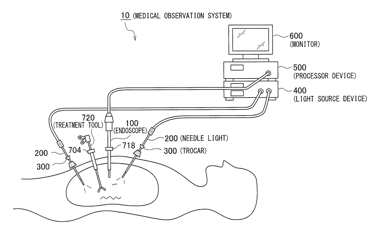
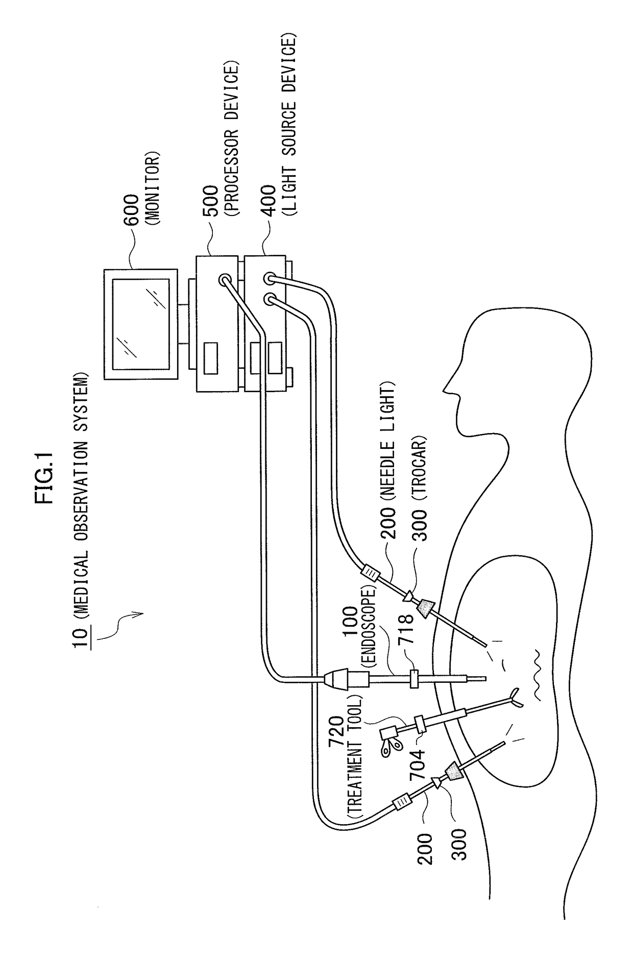
[0047]FIG. 1 is an overall configuration view illustrating one embodiment of a medical observation system. As illustrated in FIG. 1, the medical observation system 10 of the present embodiment includes an endoscope 100 configured to observe an observation target portion in a body cavity, a needle light (illuminator) 200 configured to irradiate the body cavity of a subject with illumination light, a light source device 400 configured to supply illumination light to the needle light 200, and a processor device 500 configured to generate an endoscope image. The processor device 500 is connected to a monitor 600 configured to display the endoscope image.

[Endoscope]

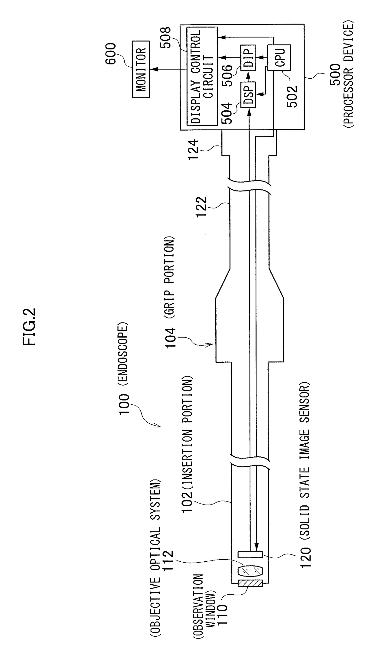
[0048]FIG. 2 is a schematic view illustrating a configuration example of the endoscope 100. The endoscope (electronic endoscope) 100 illustrated in FIG. 2 includes a rigid insertion portion 102 that is inserted into a body cavity of the subject, a grip portion 104 provided in a back end of the inser...

second embodiment

[0112]FIG. 13 is a schematic view illustrating a configuration example of a needle light according to a second embodiment. In FIG. 13, component members in common with those in FIG. 3 are designated by identical reference numerals to omit a description thereof.

[0113]As illustrated in FIG. 13, the insertion portion 202 of the needle light 200 according to the second embodiment has a bend portion (one way bend portion) 220 bendable in one direction provided between the rigid portion 210 and the front end portion 212. A shape memory alloy wire 222 in a linear shape is inserted into the one way bend portion 220. The shape memory alloy wire 222 has a two-way shape memory effect that is to contract its length by heating and to expand its length by cooling so as to restore its original length. The grip portion 204 has an operation switch 224 provided for ON / OFF control of current application to the shape memory alloy wire 222. The shape memory alloy wire 222 is electrically connected to a ...

third embodiment

[0116]FIG. 14 is a schematic view illustrating a configuration example of a needle light according to a third embodiment. In FIG. 14, component members in common with those in FIG. 3 are designated by identical reference numerals to omit a description thereof.

[0117]As illustrated in FIG. 14, the needle light 200 according to the third embodiment has a temperature sensor 226 built in the front end portion 212 of the insertion portion 202. The temperature sensor 226 detects temperature of the front end portion 212, and outputs the detected temperature to the CPU 410 of the light source device 400 through the signal line 228.

[0118]The CPU 410 of the light source device 400 obtains temperature change (temperature change rate) per unit time based on the temperature detected by the temperature sensor 226, and compares the temperature change rate with a reference value stored in a memory 416. When the temperature change rate exceeds the reference value as a result of comparison, the CPU 41...


PUM


Abstract

An endoscope and an illuminator are safely placed in a body cavity without generating a noticeable postoperative scar. A method of placing medical insertion instruments into a body cavity includes a first step of inserting, into the body cavity through a first opening formed on a body wall, an endoscope together with a first illuminator; and a second step of inserting, into the body cavity through a second opening formed at a position different from the first opening, a second illuminator. Preferably, the method further includes a third step of pulling out the first illuminator from the first opening and inserting the first illuminator into the body cavity through a third opening formed at a position different from the first and second openings.

Description

CROSS REFERENCE TO RELATED APPLICATIONS[0001]This application claims priority under U.S.C. §119(e) of U.S. Provisional Applications 61 / 710,492 filed on Oct. 5, 2012 which is incorporated herein by reference in its entirety.BACKGROUND OF THE INVENTION[0002]Field of the Invention[0003]The present invention relates to a method of placing medical insertion instruments inside a body cavity, and more particularly relates to a method of safely placing into a body cavity an endoscope for observing the inside of the body cavity and an illuminator configured separately from the endoscope to emit illumination light for illuminating the inside of the body cavity.[0004]Description of the Related Art[0005]In recent years, endoscopic surgery using a rigid endoscope (rigid mirror) such as an abdominoscope is widely performed since the endoscopic surgery is less invasive to a patient than surgery involving operation such as laparotomy and thoracotomy. For example, in laparoscopic surgery, a cylindri...

Claims


Application Information

Patent Timeline
Patent Type & Authority Patents(United States)
IPC IPC(8): A61B1/313A61B1/07A61B1/005A61B1/05A61B90/30A61B17/02A61B17/00A61B1/00A61B1/06A61B17/34
CPCA61B1/3132A61B1/0014A61B1/00052A61B1/0057A61B1/00105A61B1/00117A61B1/00158A61B1/05A61B1/06A61B1/0669A61B1/07A61B1/313A61B17/00234A61B17/0218A61B17/3423A61B90/30A61B1/00009A61B2017/3447A61B2017/3445
Inventor DEJIMA, TAKUMITORISAWA, NOBUYUKIIWASAKA, MASAYUKICURCILLO, PAUL
Owner FUJIFILM CORP
Why Eureka
Try Eureka