Foldable power strip

a power strip and foldable technology, applied in the field of power strips, can solve the problems of fixed power cords, inconvenience for consumers, and inability to adjust the power strip and cord,

Inactive Publication Date: 2017-12-12
COLEMAN CABLE INC
View PDF25 Cites 3 Cited by
  • Summary
  • Abstract
  • Description
  • Claims
  • Application Information

AI Technical Summary

Benefits of technology

[0003]The present invention comprises a foldable power strip having components that move relative to one another about a hinge or axis to allow positioning of the power strip and cord in a number of different configurations to adjust to the environment of where the power strip is used. The power strip comprises a pair of housing members hingedly connected together for rotation between an elongated open position and a folded, closed position, with the ability to be positioned at a number of positions between the open and closed positions. The power strip includes an annular ring that receives a power cord and is positioned within a hinge coupling two power strip housing members, to permit the power strip members and power cord to each be independently rotated relative to one another. The housing members may also include side members on their inside walls that include arcuate sections that together define a recess or groove for receiving the power cord therein to protect it when the power strip housing members are in the closed position.
[0004]Accordingly, it is an object of the present invention to provide a foldable power strip that is economical and easy to manufacture and use.
[0005]Yet another object of the present invention is to protect the power cord connection to the power strip when in the closed position.
[0007]A further object of the present invention is to provide a foldable power strip that allows for the power cord to be independently rotated relative to the power strip members.

Problems solved by technology

However, these devices have fixed power cords and do not permit adjustment of the power strip and cord into different positions relative to one another.
This leads to a consumer having to purchase multiple power strips or be inconvenienced by the size or shape of the power strip and the location of the cord extending outward therefrom.

Method used


Image

  • Foldable power strip
  • Foldable power strip
  • Foldable power strip

Examples


Embodiment Construction

[0016]While this invention is susceptible of embodiment in many different forms, there is shown in the drawings and will herein be described in detail several specific embodiments, with the understanding that the present disclosure is to be considered merely an exemplification of the principles of the invention and the application is limited only to the appended claims.

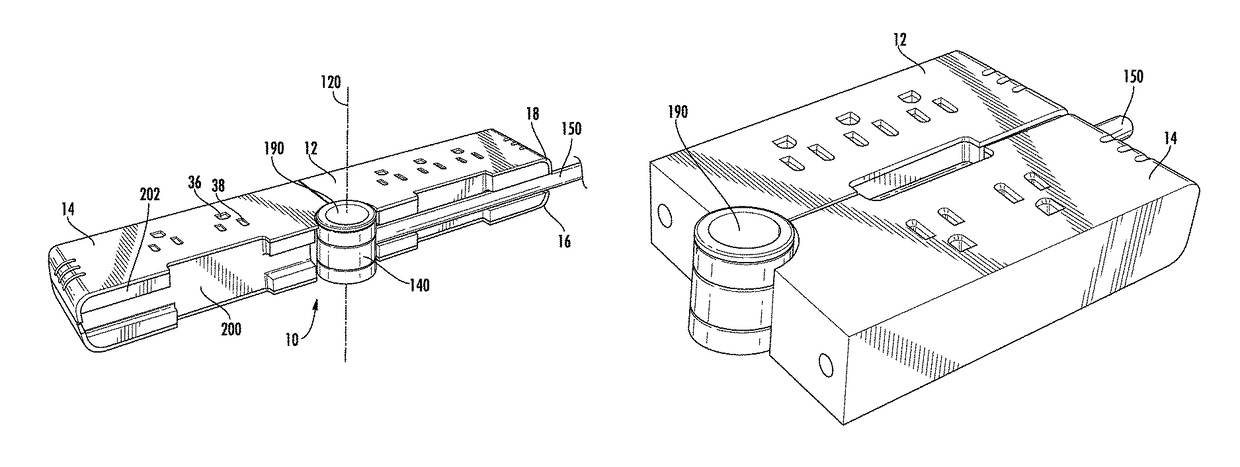
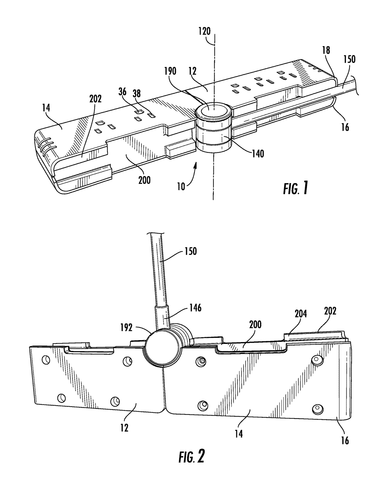
[0017]FIGS. 1 and 2 show one embodiment of the foldable power strip 10 of the present invention having a first housing member 12, a second housing member 14 and a power cord assembly 140 separately pivotable relative to one another about a vertical axis 120.

[0018]Each of the housing members 12, 14 includes a lower portion 16 and an upper portion 18 that may be attached to one another to form the housing. The lower and upper portions may be made out of a variety of materials including, but not limited to, Acrylonitrile Butadiene Styrene (“ABS”). Referring to FIGS. 4 and 5, the lower portions 16 and upper portions 18 ma...


PUM


Abstract

A foldable power strip having a pair of housing members having one or more outlets thereon and being rotationally connected together about a hinge or vertical axis. A power cord housing is also connected about the hinge or vertical axis to permit the housing members and power cord to be independently rotated relative to one another. The inside walls of the housing members may include side members that define a recess for receiving and protecting the power cord when the housing members are in the closed position.

Description

FIELD OF THE INVENTION[0001]This invention relates generally to power strips and still more particularly to foldable power strips.BACKGROUND OF THE INVENTION[0002]Power strips are prevalently used to provide power to a number of different electrical devices attached thereto. Because of the different locations and applications where such power strips may be used, it has been known to have power strips of varying sizes and shapes. However, these devices have fixed power cords and do not permit adjustment of the power strip and cord into different positions relative to one another. This leads to a consumer having to purchase multiple power strips or be inconvenienced by the size or shape of the power strip and the location of the cord extending outward therefrom.BRIEF SUMMARY OF THE INVENTION[0003]The present invention comprises a foldable power strip having components that move relative to one another about a hinge or axis to allow positioning of the power strip and cord in a number o...

Claims


Application Information

Patent Timeline
Patent Type & Authority Patents(United States)
IPC IPC(8): H01R25/00H01R27/02H01R31/00H01R33/00
CPCH01R25/003
Inventor IRBE, TRISHASABATO, DANIELKU, SHIAO-TSUN
Owner COLEMAN CABLE INC
Why Eureka
Try Eureka