
Limiting assembly for a self-adjusting heavy duty clutch

a clutch and self-adjusting technology, applied in the direction of friction clutches, mechanical actuated clutches, clutches, etc., can solve the problems of increasing the distance between the pressure plate and the driven member, the clutch components wear down from constant engagement and disengagement, and the problem of cam rings over-adjusting, so as to facilitate the placement of the strap on the bushing, the effect of preventing the cam rings from over-adjusting

Active Publication Date: 2018-10-09
ILLINOIS AUTO TRUCK CO INC
View PDF32 Cites 0 Cited by
  • Summary
  • Abstract
  • Description
  • Claims
  • Application Information

AI Technical Summary

Benefits of technology

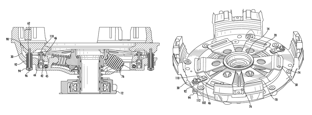
The present invention is a self-adjusting friction clutch that prevents overadjustment of the cam rings caused by sudden impact to the vehicle. The limiting mechanism connects the pressure plate to the adjustment mechanism using straps that link fixation members together, which prevents unintended adjustment of the cam rings and minimizes clutch maintenance. The technical effects of the invention include economic and easy-to-use, inhibiting unintended adjustment of the cam rings, and maintaining constant adjustment of the clutch.

Problems solved by technology

Over time, components of clutches wear down from constant engagement and disengagement during use.
After a period of use, wear on the friction surface of the driven member causes the distance between the pressure plate and driven member to increase.
While such self-adjusting clutches work, problems have arisen during their use and operation in the field.
In particular, it has been known for the cam rings to jump when there is a sudden impact to a vehicle (e.g., when a truck hits a loading dock when backing up), thereby causing an overadjustment of the cam rings due to the increased distance caused by the impact.
The overadjustment shortens the life of the clutch and diminishes its value.

Method used


Image

  • Limiting assembly for a self-adjusting heavy duty clutch
  • Limiting assembly for a self-adjusting heavy duty clutch
  • Limiting assembly for a self-adjusting heavy duty clutch

Examples


Embodiment Construction

[0023]While this invention is susceptible of embodiment in many different forms, there is shown in the drawings and will herein be described in detail several specific embodiments, with the understanding that the present disclosure is to be considered merely an exemplification of the principles of the invention and the application is limited only to the appended claims.

[0024]It is appreciated that the limiting mechanism of the present invention may be used with a variety of self-adjusting clutch assemblies utilizing cam rings to prevent the cam rings from over-adjusting upon a sudden impact including, but not limited to, the clutch assemblies shown and disclosed in U.S. Pat. No. 5,566,804, the entirety of which is hereby incorporated by reference.

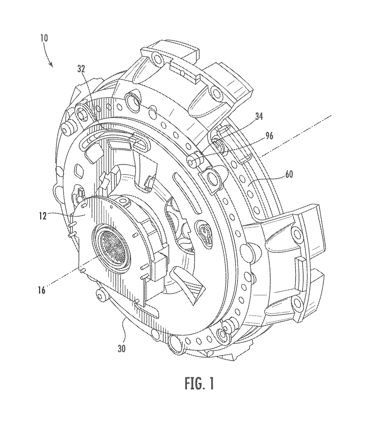
[0025]Clutch assembly 10 is designed to selectively transmit torque from a vehicle's engine to a driven shaft. In particular, a release assembly 12 allows for the clutch assembly to be selectively disengaged from the flywheel (typically thr...


PUM


Abstract

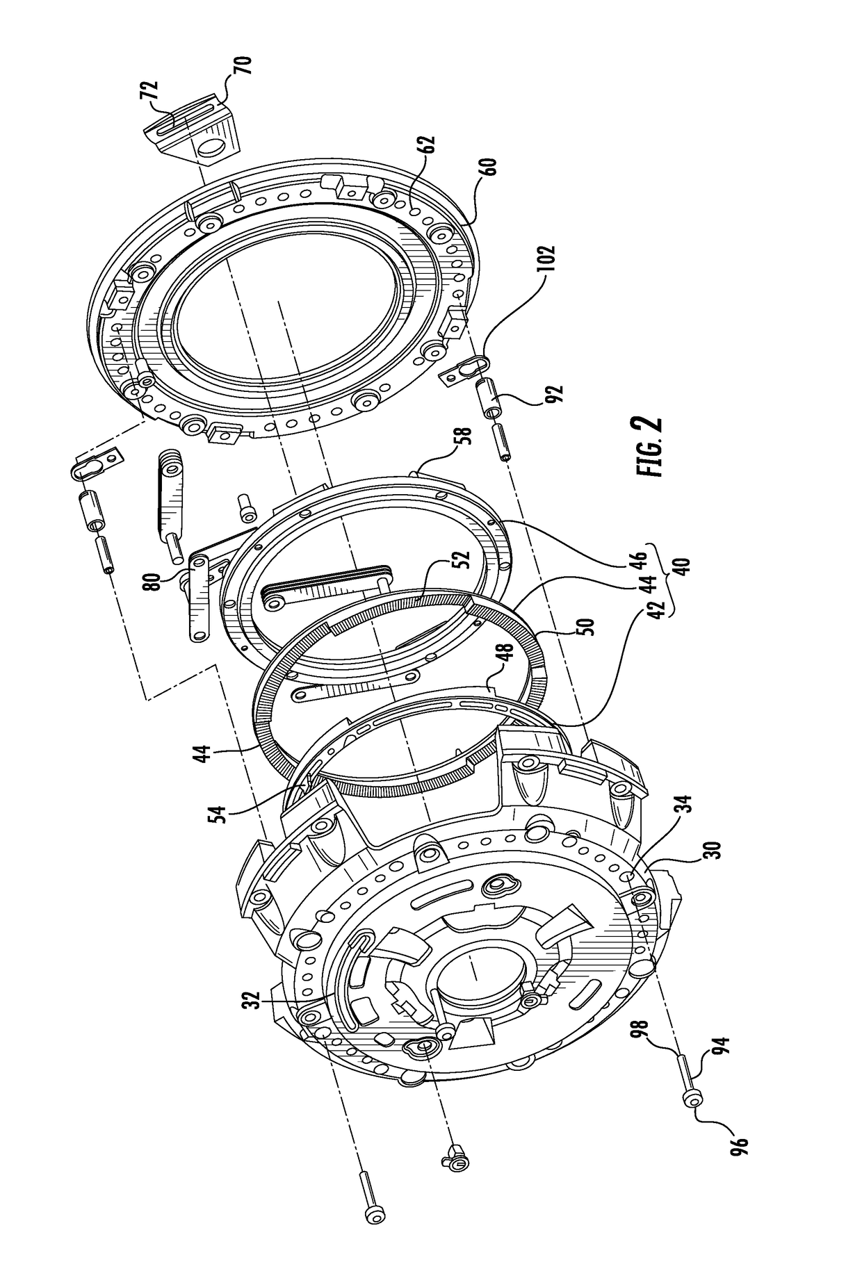
A limiting mechanism or assembly for a self-adjusting friction clutch to prevent the overadjustment of cam rings caused by a sudden impact to the vehicle. The limiting mechanism connects the cover to the adjustment mechanism using straps that link fixation members together. In one embodiment, a first fixation member comprises a bolt that attaches a bushing, which is placed through a corresponding hole in the cover of the clutch, relative to the pressure plate and a second fixation member comprises a bolt that engages a corresponding hole on the adjusting ring.

Description

RELATED APPLICATION[0001]This application claims the benefit of U.S. provisional patent application Ser. No. 62 / 267,040, filed Dec. 14, 2015, the entirety of which is hereby incorporated by reference.FIELD OF THE INVENTION[0002]This invention relates generally to self-adjusting friction clutches and, more particularly, to self-adjusting friction clutches that have a limiting mechanism or assembly to prevent unintended over adjustments of the clutches.BACKGROUND OF THE INVENTION[0003]Clutches engage and disengage two moving parts relative to one another. In vehicles, clutches are used to change gears to control the amount of power that is transferred from the vehicle's engine to the transmission to make the vehicle move. In particular, a pressure plate removably engages a drive member attached to a clutch flywheel connected to the engine crankshaft. Disengagement of the clutch by depressing the clutch pedal releases the pressure plate from contact with the drive member to allow the g...

Claims


Application Information

Patent Timeline
Patent Type & Authority Patents(United States)
IPC IPC(8): F16D13/75
CPCF16D13/757
Inventor STEIN, RICHARD H.STEIN, JORDAN R.ANTA, CORYSAAF, STEVETIKHONOV, VADIM
Owner ILLINOIS AUTO TRUCK CO INC
Learn More