Motor control apparatus generating command limited by motor torque

a motor control apparatus and torque technology, applied in the direction of electric programme control, program control, instruments, etc., can solve the problems of limited acceleration, deterioration of positioning accuracy, and inability to perform sufficient acceleration matching with the performance in the low-speed range of the motor, so as to achieve efficient use of motor performan

Active Publication Date: 2016-05-12
FANUC LTD
View PDF3 Cites 5 Cited by
  • Summary
  • Abstract
  • Description
  • Claims
  • Application Information

AI Technical Summary

Benefits of technology

[0031]According to the present invention, the motor control apparatus can be realized which can bring a torque generated in the motor in various operation states close to the allowable torque and efficiently use the motor performance. According to the present invention, the torque generated in the motor in vari...

Problems solved by technology

In addition, rapid acceleration and deceleration gives a large impact to the movable body and causes deterioration in positioning accuracy.
Thus, acceleration is limited by acceleration and deceleration processing in an actual command.
However, the two-stage moving average-type acceleration and deceleration processing based on the formula 2 is limited by an acceleration and deceleration performance in a high-speed range of the motor, and thus, sufficient acceleration matching with the performance cannot be performed in a low-speed range of the motor.
In other words, a fairly large part of the acceleration performance is not utilized in the low-speed range, which causes a disadvantage that an extra time is required for positioning and acceleration and deceleration before and after the positioning.
According to the moving average-type acceleration and deceleration processing, when the acceleration response sufficiently and immediately follow...

Method used


Image

  • Motor control apparatus generating command limited by motor torque
  • Motor control apparatus generating command limited by motor torque
  • Motor control apparatus generating command limited by motor torque

Examples


Embodiment Construction

[0050]The motor control apparatus which generates a command limited by a motor torque will be described below with reference to the drawings. However, it is noted that the present invention is not limited by the drawings and the embodiment described below.

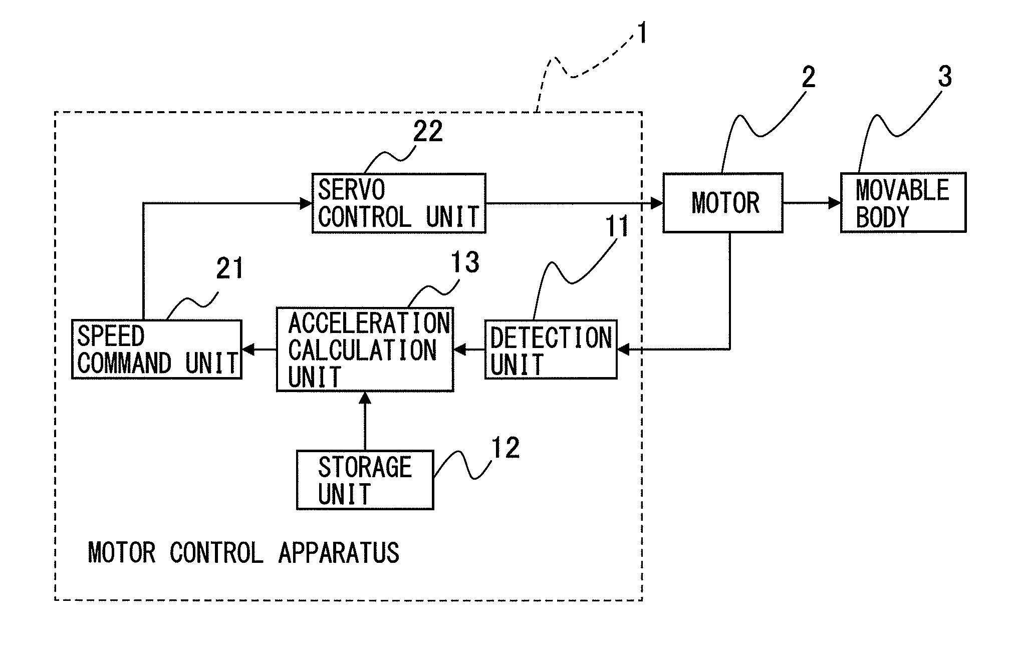
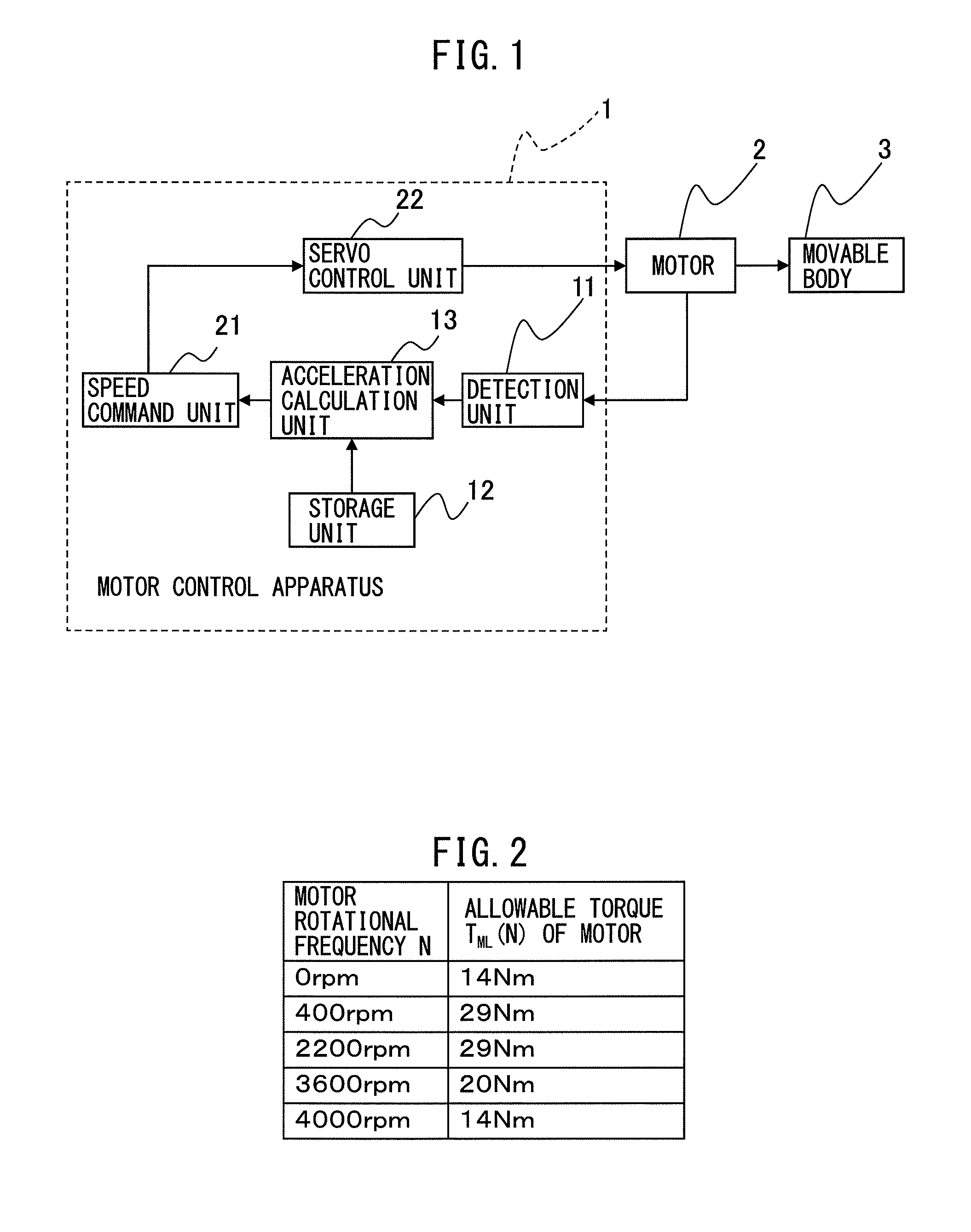
[0051]FIG. 1 is a block diagram illustrating the motor control apparatus according to the embodiment. A model is described as an example in which a motor 2 is connected to a ball screw by a coupling and a table as a movable body 3 is attached to a nut of the ball screw. According to the present embodiment, the movable body 3, which is a table, linearly moves in a vertical direction, and thus the gravity constantly acts in one direction (i.e., a downward direction) on the movable body 3 linearly moving in the vertical direction. In addition, the model has a mechanical structure in which a frictional force is generated in a direction opposite to the moving direction of the movable body 3 when the movable body 3 linearly moves. Accord...


PUM


Abstract

A motor control apparatus includes a detection unit detecting a motor rotational frequency, a storage unit storing an allowable torque at the motor rotational frequency detected by detection unit, a first torque offset generated in a direction opposite to a moving direction of a movable body, a second torque offset generated in one direction regardless of the moving direction of the movable body, a rotor inertia moment, a load inertia moment, and a conversion factor for converting a motor rotation angle in rotary motion of the motor to a moving distance in linear motion of the movable body, and an acceleration calculation unit calculating an acceleration command of the motor for each moving direction of the movable body and each acceleration operation and deceleration operation using the allowable torque, the first torque offset, the second torque offset, the rotor inertia moment, the load inertia moment, and the conversion factor.

Description

BACKGROUND OF THE INVENTION[0001]1. Field of the Invention[0002]The present invention relates to a motor control apparatus which controls a motor connected to a movable body as a driving source to linearly move the movable body.[0003]2. Description of the Related Art[0004]In a structure which moves a movable body by connecting to a motor, a servo control loop is constituted in which a motor control apparatus generates a position command or a speed command with respect to a rotor of the motor to control the motor, and information about a rotor position and a rotor speed of the motor obtained from an encoder attached to the motor is fed back to the motor control apparatus. The above-described structure includes, for example, a structure in which a motor is connected to a ball screw by a coupling and a table as a movable body is attached to a nut of the ball screw.[0005]In the above-described servo control loop, when a stepwise speed command is given, acceleration at a start of the com...

Claims


Application Information

Patent Timeline
IPC IPC(8): G05B19/416
CPCG05B19/416G05B2219/43045G05B19/19G05B19/408
Inventor UEMATSU, HIDETOSHI
Owner FANUC LTD
Why Eureka
Try Eureka