
Security device for hinged products

a technology of security devices and hinged products, which is applied in the direction of burglar alarm mechanical actuation, lock applications, instruments, etc., can solve the problems of not being favored by retailers and other business establishments, cumbersome brackets and cables, and not being aesthetically pleasing,

Inactive Publication Date: 2009-12-29
VANGUARD PRODS GROUP
View PDF33 Cites 12 Cited by
  • Summary
  • Abstract
  • Description
  • Claims
  • Application Information

AI Technical Summary

Benefits of technology

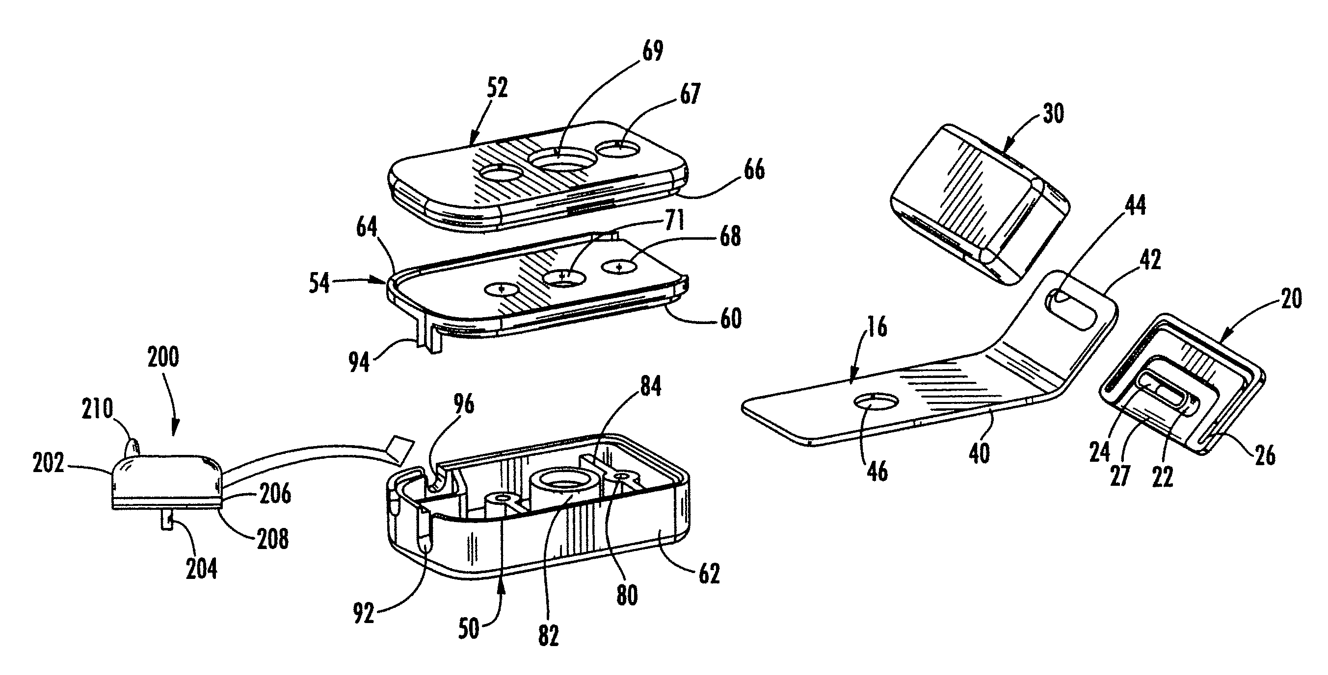
[0008]A hole extending through the plate is sized to receive the elongated body of a fastener for connecting the plate to the second anchor assembly. The second anchor assembly may include a base and a lid assembly that may be attached together by a pair of fasteners and that include a slot for receiving the plate. In one embodiment, the lid assembly includes a pair of holes that have an upper portion sized to permit the head of the fastener to be recessed within the bottom of the lid assembly. The lower portion is sized so that the fastener head may not pass therethrough. Accordingly, once the plate is inserted into the corresponding slot of the second anchor assembly, the plate will cover and prevent access to the fastener heads.
[0017]It is yet another object of the present invention to produce a security device that is economical and easy to manufacture and use.

Problems solved by technology

While such devices may work, the brackets and cable are often cumbersome and are not aesthetically pleasing (e.g., for use in store displays).
Accordingly, such devices are not favored by retailers and other business establishments who desire the product to be picked up and examined by potential purchasers, in as close to actual use conditions as possible.
While these systems may work, they were not well received by the business community because they lacked a mechanical tether.
However, such systems permit the computers to be stolen by breaking off part of the computer about the KENSINGTON port, thereby leaving the laptop housing damaged, but not affecting the operability of the computer.

Method used


Image

  • Security device for hinged products
  • Security device for hinged products
  • Security device for hinged products

Examples


Embodiment Construction

[0031]While this invention is susceptible of embodiment in many different forms, there is shown in the drawings and will herein be described in detail several specific embodiments, with the understanding that the present disclosure is to be considered merely an exemplification of the principles of the invention and the application is limited only to the appended claims.

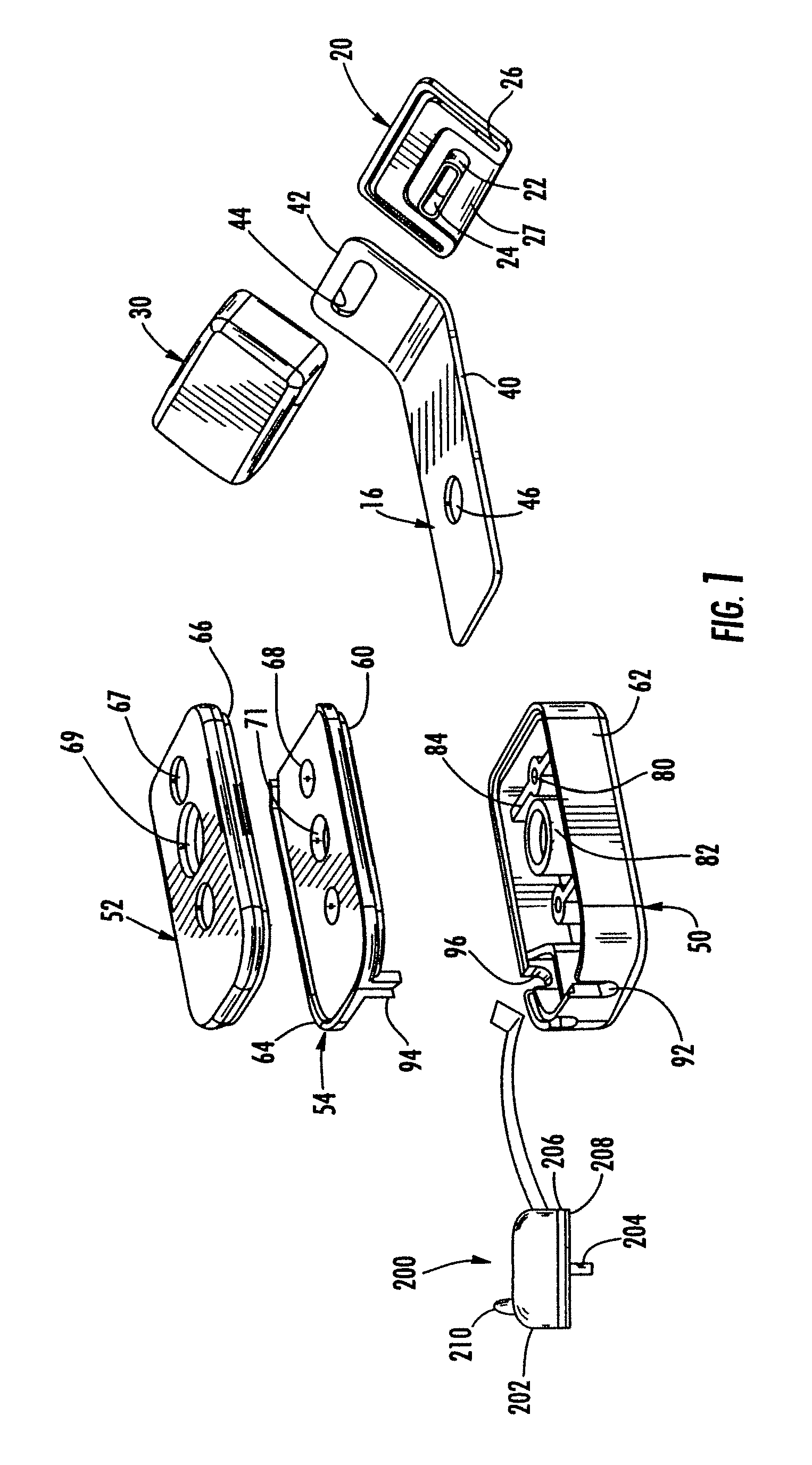
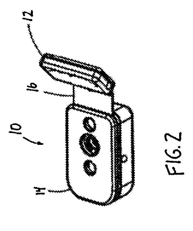
[0032]Referring now to the drawings, and particularly to FIGS. 1 through 5, there is shown one embodiment of the present invention. The security device of the present invention, generally designated by the number 10, is shown in FIGS. 2 and 4 as having a first anchor assembly 12, a second anchor assembly 14, a band or plate 16, and a tether or cord 18 for mechanically and / or electronically securing the security device. While the embodiment disclosed herein refers to a laptop computer, it is appreciated that the security device may be used with any type of hinged electronic product including, but not limited to, portab...


PUM


Abstract

A security device for preventing theft of a hinged electronic product comprising a band that is inserted through the open area about the hinge of the product and a pair of anchor assemblies that are attached to the ends of the band. A tether or cable attaches the security devices to an object to permit the hinged product to be moved over a limited distance. The security device also is connected to an alarm system so that removal or tampering with the band activates the alarm. Filaments and contacts may also be used to detect the presence of the band within the second anchor assembly. An indicator may also provide notice when the security device is armed and / or tampered with.

Description

[0001]This application claims the benefit of U.S. provisional patent application Ser. No. 60 / 824,301, filed Sep. 1, 2006.FIELD OF THE INVENTION[0002]This invention relates in general to security and anti-theft devices, and more particularly, to a security device for a hinged electronic product or device to prevent theft of such item.BACKGROUND OF THE INVENTION[0003]In order to deter and prevent the theft of various hinged electronic items such as laptop computers and portable DVD players and the like from offices, houses and other establishments, various security devices and systems have been developed. One known security device comprises a bracket assembly that captures the laptop about its hinge and is fixedly attached to a table or other object to prevent movement of the hinged device. It is also known to use a cable that encircles the hinge in place of the brackets. While such devices may work, the brackets and cable are often cumbersome and are not aesthetically pleasing (e.g.,...

Claims


Application Information

Patent Timeline
IPC IPC(8): G08B13/08
CPCG08B13/1445Y10T70/5009
Inventor KELSCH, CHRISTOPHER A.FIGH, JR., JOHN N.BEACH, THOMAS J.SWARTWOOD, LUCAS P.FARLAND, MICHAEL D.
Owner VANGUARD PRODS GROUP
Learn More