
Daylight harvesting light fixture and control system for same

a technology of electronic control system and light fixture, which is applied in the direction of lighting apparatus, electric lighting source, electric lighting source, etc., can solve the problems of unsolved problems such as the limitation of current daylight harvesting technology to use daylight photosensors, the difficulty of installation and maintenance of daylight harvesting illumination by external lights, and the difficulty of achieving daylight harvesting illumination to da

Active Publication Date: 2017-12-26
DMF
View PDF8 Cites 23 Cited by
  • Summary
  • Abstract
  • Description
  • Claims
  • Application Information

AI Technical Summary

Problems solved by technology

Current daylight harvesting technology is limited to use of daylight photosensors external to the electric light fixtures in an effort to minimize introduction of artificial light into the measurement of available ambient daylight.
Wall and ceiling mounted photosensor modules external to the electric light fixtures complicate installation and maintenance of daylight harvesting illumination.
Such installation presents difficulties which to date have remained unsolved.
This is a significant disadvantage as many interchangeable ornamental trim pieces exist in standard sizes which could not be used without the special opening for the sensor.
Even if an opening is provided, the orientation of the trim piece then becomes restricted by the location of the sensor, so that square trim pieces, for example, could not be aligned with walls unless care was taken to install the entire fixture in correct orientation.

Method used


Image

  • Daylight harvesting light fixture and control system for same
  • Daylight harvesting light fixture and control system for same
  • Daylight harvesting light fixture and control system for same

Examples


Embodiment Construction

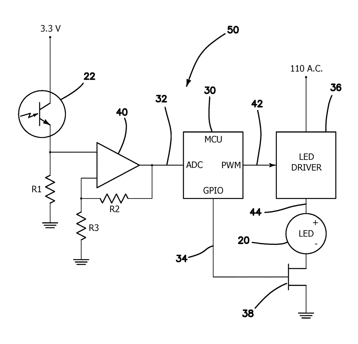
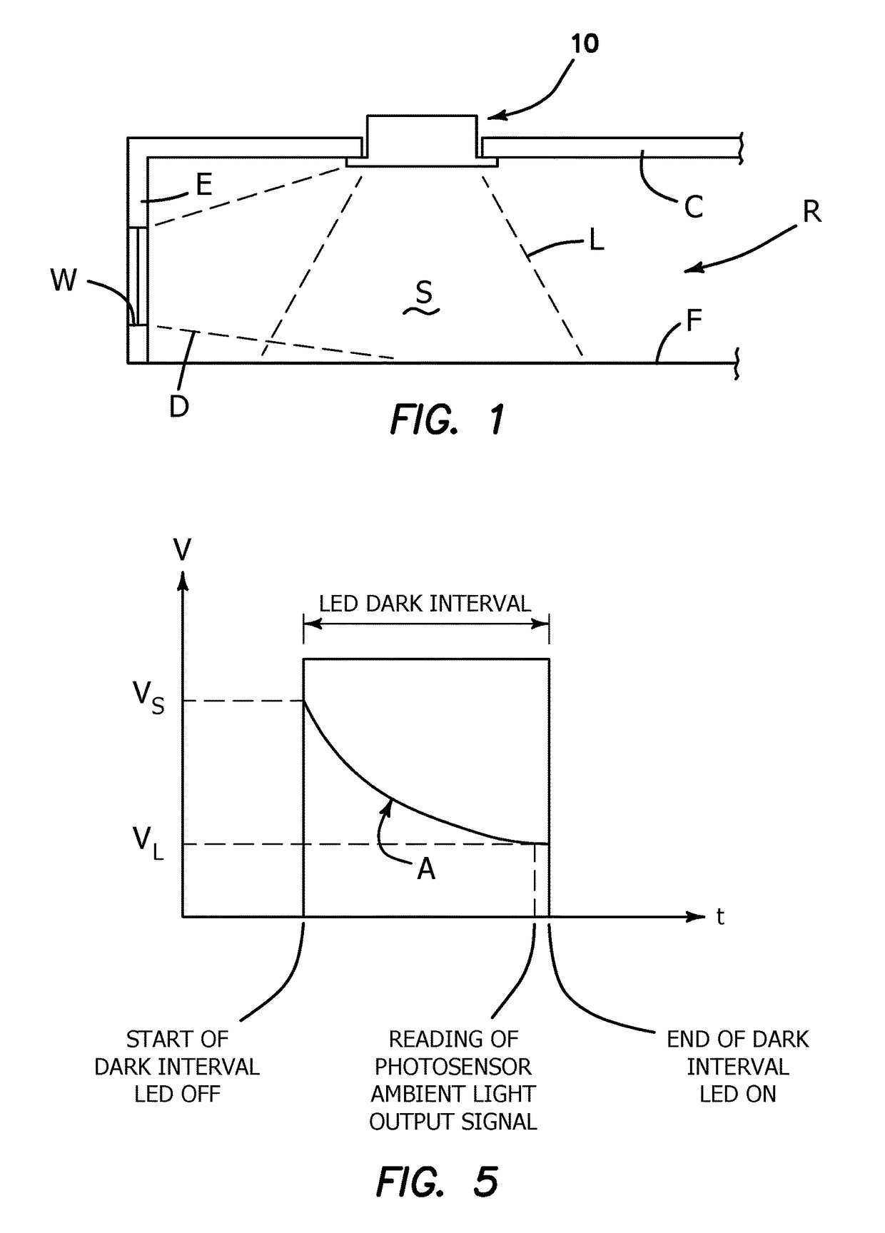
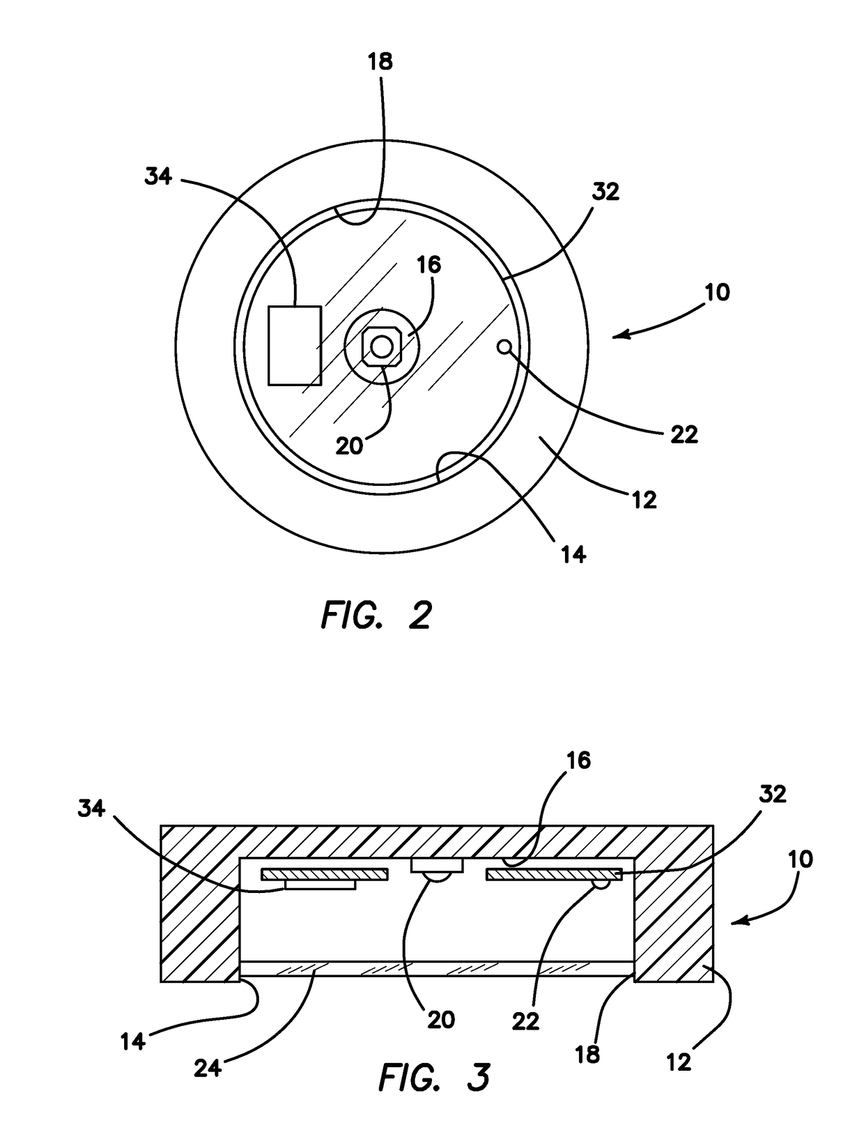
[0012]With reference to the accompanying drawings, in which like elements are designated by like numerals, FIG. 1 is a schematic representation of an enclosed interior space or room R, with an end wall E in which a window W admits natural daylight D. A daylight harvesting lamp module 10 according to this invention is installed in ceiling C above a floor F for illuminating a space S (the illuminated space) generally underlying the lamp module 10 in room R. At different times of day space S in room R is illuminated by either or both of natural daylight D admitted through window W and artificial light L produced by lamp module 10.

[0013]Illumination of space S includes artificial illumination provided by lamp module 10 in combination with ambient illumination. Ambient illumination is defined here as existing illumination in space S without any contribution from module 10. In a simple situation where a single module 10 is the sole source of artificial light in space S, ambient illuminati...


PUM


Abstract

A daylight harvesting light fixture has a housing defining a light aperture, a light emitting diode (LED) in the housing for providing illumination through the aperture, a power supply for supplying drive current to the LED; a photosensor for sensing ambient illumination through the housing aperture, and a control circuit programmed and connected for a) turning off current to the LED for a dark interval imperceptible to the human eye; b) deriving an ambient illumination level signal based on the photosensor output while the LED is turned off; c) calculating an LED light output complementary to measured ambient illumination to achieve a target ambient illumination; and d) restoring drive current to the LED at a level adjusted to produce the calculated complementary LED light output. This sequence may be repeated periodically to maintain a target ambient illumination.

Description

FIELD OF THE INVENTION[0001]This invention concerns lighting control systems and more particularly relates to improvements in daylight harvesting light fixtures and electronic control systems for the same.STATE OF THE PRIOR ART[0002]Energy for interior illumination can be conserved by limiting artificial light to no more than needed for supplementing available daylight to achieve a desired or target level of interior lighting. Since available daylight illumination varies continuously over the course of the day it becomes necessary to adjust the artificial light complement accordingly in order to maintain a constant combined level of illumination. This technique of supplementing available daylight with electric light has come to be known as daylight harvesting. Substantial energy savings can be realized by this method.[0003]Current daylight harvesting technology is limited to use of daylight photosensors external to the electric light fixtures in an effort to minimize introduction of...

Claims


Application Information

Patent Timeline
Patent Type & Authority Patents(United States)
IPC IPC(8): H05B33/08H05B37/02H05B44/00
CPCH05B33/0854H05B37/0218H05B47/11Y02B20/40H05B45/12
Inventor KASHANI, OREN
Owner DMF
Learn More