Smart shunt devices and methods

a smart shunt and shunt technology, applied in the field of smart shunts, can solve the problems that the flow meters employing two sensors lack sufficient stability in some applications, and achieve the effect of reducing brain surgeries

Inactive Publication Date: 2018-01-09
NEW JERSEY INSTITUTE OF TECHNOLOGY
View PDF8 Cites 0 Cited by
  • Summary
  • Abstract
  • Description
  • Claims
  • Application Information

AI Technical Summary

Benefits of technology

[0005]It would be particularly advantageous for doctors to know about the composition, flow and pressure characteristics of the fluid to understand clinical dangers facing a patient. For example, it would be valuable to know if the flow is decreasing in a way that indicates that an occlusion is beginning to form. Patients would benefit from a therapy that cleared out the shunt tube to restore fluid flow without an operation. Patients and doctors would benefit from information that would allow timely scheduling of surgery to repair a shunt and also from information that would indicate that surgery is unnecessary. Patients and doctors would benefit from a shunt control valve which automatically adjusts to conditions in the tube. Patients and doctors would benefit from the availability of information about the patient at locations remote from the doctors' offices.
[0008]Prior art flow meters which employ two sensors lack sufficient stability in some applications where the flow is slow or lack sufficient range of the parameters that they can measure. External sources of variation include gravitational and temperature differences between the separate sensors. The single sensor embodiment in the presently disclosed flow meter solves these problems. The differential membrane single-capacitor flow meter disclosed herein eliminates the stability problem because there is a negligible hydrostatic pressure difference between the two sides of the membrane. The flexible membrane responds only to the drop in pressure from the flow, F, when the fluid passes the plate first, P1, then loops back and passes again at P2 after a calibrated flow resistance R:P1−P2=R*F. The capacitor forms part of a resonant circuit that can be implanted and requires no internal power, so it can remain in place for decades, in principle. An external reader couples inductively to the internal circuit and can measure very small shifts in the resonant circuit corresponding to small changes in flow. The uni-capacitor devices disclosed herein can measure very small flows. The devices can measure flow continuously and therefore can make dynamic measurements of bodily functions such as pulsatility (oscillations) in the flow of fluid in the brain (cerebrospinal fluid) or the eye (intra-ocular fluid). The presently disclosed devices provide flow readings that are insensitive to the orientation of the patient's position, i.e., lying, standing or sitting.
[0010]The presently disclosed uni-capacitor devices satisfy the medical device requirement of the International Standards Organization (ISO) that a device should survive immersion under two meters of water. Prior art dual capacitor devices would not satisfy ISO requirements because each of the sensitive membranes would be pinned to the fixed capacitor plate, potentially permanently, by a large or very small background pressure. The uni-capacitor devices disclosed herein satisfy ISO requirements. The subject device is more sensitive than prior art dual capacitor devices because the capacitor gap and the flexible plate thickness can be decreased without fear of collapse at normal ambient pressures. The design also permits one to raise the Q of the resonance.
[0012]In accordance with a further aspect the systems may employ wireless information transfer. In one embodiment devices in accordance with the present disclosure are operable to reduce stray signals that obscure the measurement of flow by a factor of over 100.
[0020]Devices and methods in accordance with the present disclosure are operable to head off brain injury and death, reduce brain surgeries and test medicines.

Problems solved by technology

Prior art flow meters which employ two sensors lack sufficient stability in some applications where the flow is slow or lack sufficient range of the parameters that they can measure.

Method used


Image

  • Smart shunt devices and methods
  • Smart shunt devices and methods
  • Smart shunt devices and methods

Examples


Embodiment Construction

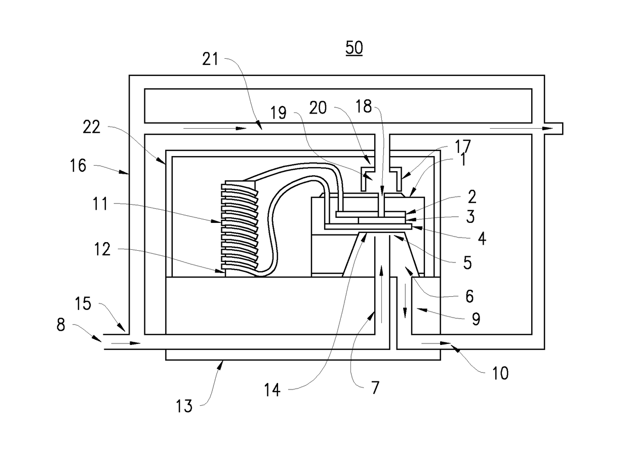
[0053]The following is a detailed description of the invention provided to aid those skilled in the art in practicing the present invention. Those of ordinary skill in the art may make modifications and variations in the embodiments described herein without departing from the spirit or scope of the present invention. Unless otherwise defined, all technical and scientific terms used herein have the same meaning as commonly understood by one of ordinary skill in the art to which this invention belongs. The terminology used in the description of the invention herein is for describing particular embodiments only and is not intended to be limiting of the invention. All publications, patent applications, patents, figures and other references mentioned herein are expressly incorporated by reference in their entirety.

[0054]As will be apparent to those skilled in the art, the terms “sensor” and “capacitor” may be used interchangeably when a capacitor is used as a sensor or vice-versa.

Uni-Cap...


PUM

PropertyMeasurementUnit
flow rateaaaaaaaaaa
resonant frequencyaaaaaaaaaa

Abstract

Devices and methods for the measurement and control of fluid using one or two capacitors are described. The devices use Micro-Electro-Mechanical-Systems (MEMS) and radio-frequency inductive coupling to sense the properties of a fluid in a tube. The single and double capacitor devices may be coupled to shunts implantable in a patient and operable to be interrogated non-invasively. The shunts employing the novel capacitor devices are insensitive to stray signals such as the orientation of a patient's head. The devices are operable to employ a wireless external spectrometer to measure passive subcutaneous components.

Description

CROSS-REFERENCE TO RELATED APPLICATIONS[0001]This application claims the benefit of U.S. Provisional Patent Application No. 61 / 781,606 filed Mar. 14, 2013, the entirety of which is incorporated herein by reference.STATEMENT REGARDING FEDERALLY SPONSORED RESEARCH[0002]The research leading to the present invention was supported in part by grants from the National Institutes of Health (NIH 1479-S002 and NINDS R43NS056628-01A2). The United States Government has certain rights in the invention.FIELD OF THE INVENTION[0003]The invention relates to smart shunts and methods of making and using same.BACKGROUND[0004]There are applications where there is a need for measuring the properties of a fluid in a tube of a shunt when the orientation and background pressure of the device cannot be accurately controlled, such as in the human body. Examples include the intracranial fluid (in the human brain) and the intraocular fluid (in the human eye). There are medically important features in both cases...

Claims


Application Information

Patent Timeline
Patent Type & Authority Patents(United States)
IPC IPC(8): G01L9/12G01L9/00G01F1/64A61F9/007A61M27/00
CPCA61F9/00781G01F1/64G01L9/007G01L9/0072G01L9/0073A61M2205/3344A61M27/006A61M2205/0244A61M2205/3327
Inventor THOMAS, GORDON ALBERTFARROW, REGINALD CONWAYKANWAL, ALOKIK
Owner NEW JERSEY INSTITUTE OF TECHNOLOGY
Why Eureka
Try Eureka