Method of starting gas delivery from a liquefied gas fuel system to a gas operated engine and a liquefied gas fuel system for a gas operated engine

a gas operated engine and liquefied gas technology, applied in the direction of liquid handling, container discharging methods, packaged goods types, etc., can solve the problems of limited heat available after bunkering, difficult to start gas delivery, and long time-consuming pressure buildup, etc., to achieve rapid bunkering

Active Publication Date: 2018-01-09
WARTSILA FINLAND OY
View PDF11 Cites 6 Cited by
  • Summary
  • Abstract
  • Description
  • Claims
  • Application Information

AI Technical Summary

Benefits of technology

[0017]This way stating and running the engines on gas when the available heat power is small is made possible. Also this ensures that all heat available can and will be used for increasing and maintaining gas pressure.
[0029]Low counter pressure in the tank allows more rapid bunkering and tank's operating pressure is maintained immediately after bunkering with minimum need of pressure build up system.

Problems solved by technology

Particularly but not exclusively natural gas (NG) is feasible due to its availability.
Usually natural gas is stored as liquefied natural gas (LNG) at temperature of about −162° C., thus the storage cause problems particularly when the LNG is stored at high pressure, about at 5 bar, which is typically the level that a gas operated piston engine requires.
If the engines of the vessel are not running or are only idling there is only a limited heat available after bunkering.
This means that the pressure build up takes a long time.

Method used


Image

  • Method of starting gas delivery from a liquefied gas fuel system to a gas operated engine and a liquefied gas fuel system for a gas operated engine
  • Method of starting gas delivery from a liquefied gas fuel system to a gas operated engine and a liquefied gas fuel system for a gas operated engine
  • Method of starting gas delivery from a liquefied gas fuel system to a gas operated engine and a liquefied gas fuel system for a gas operated engine

Examples


Embodiment Construction

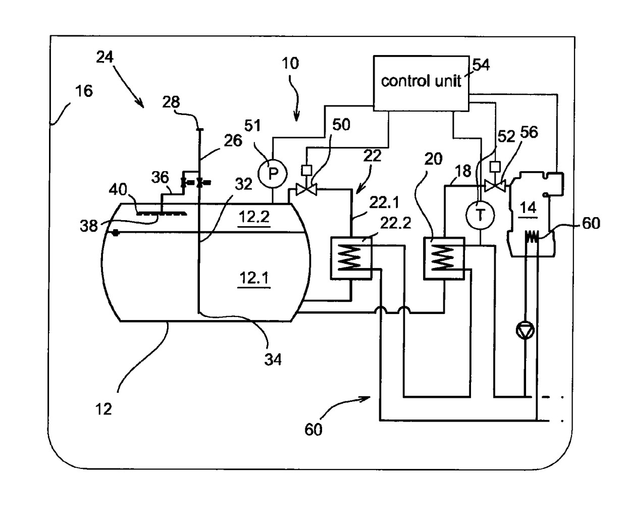
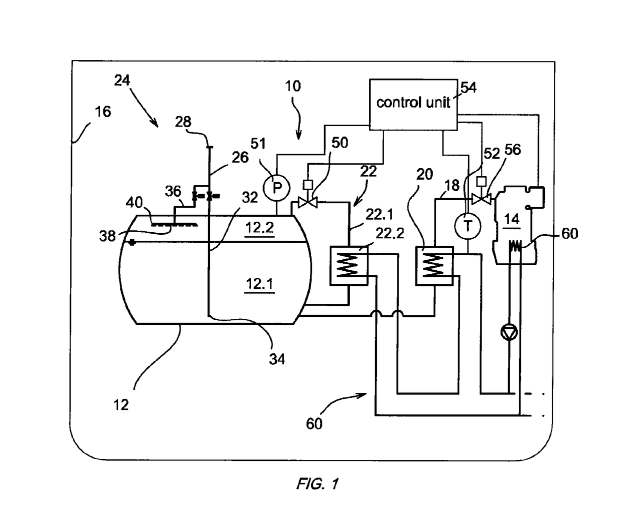
[0035]FIG. 1 describes an embodiment of the fuel system 10 according to the invention. The fuel system comprises a fuel tank 12 which is in connection with at least one gas operated engine 14 of the vessel 16, so that the engine may be operated making use of the gas stored in the fuel tank. The gas, particularly liquefied natural gas, is stored in the tank 12 at considerably low temperature, typically at temperature of about −162° C. which is described as cryogenic conditions. Typically the gas fills the tank so that a part of the gas is as liquefied gas at the bottom of the tank 12.1 and part as gaseous gas at the upper part 12.2 i.e. gas space of the tank above the liquid portion of the gas. The tank 12 comprises insulation (not shown) to prevent excessive warming up of the LNG in the tank arrangement. The fuel system 10 is filled from time to time and the filling procedure is performed such that after the filling the tank 12 is pressured having an adequate pressure to at least st...


PUM


Abstract

A method for starting gas delivery from a liquefied gas fuel system includes a fuel tank filled with liquefied gas by a filling procedure and the filling procedure resulting in the pressure in the tank being at least at an operational pressure required by the engine. The method pressure in the tank is controlled by controlling the operation of a pressure build up system including the pressure build up evaporator which is arranged in a conduit leading from the bottom section of the tank to the upper section of the tank. The pressure build up system is controlled by controlling the flow rate of the evaporated gas in the conduit while the heat transfer medium is allowed to flow unconstrained through the pressure build up evaporator.

Description

CROSS REFERENCE TO RELATED APPLICATIONS[0001]This application is a national stage filing under section 371 of International Application No. PCT / FI2012 / 051245 filed on Dec. 14, 2012, and published in English on Jun. 19, 2014, as WO 2014 / 091061 A1, the entire disclosure of this application being hereby incorporated herein by reference.TECHNICAL FIELD[0002]The invention relates to of starting gas delivery from a liquefied gas fuel system to gas operated engine.[0003]The invention relates to a liquefied gas fuel system for a gas operated engine.BACKGROUND ART[0004]Gas is becoming more and more attractive fuel for ships' and other marine vessels' prime movers and auxiliary engines. Particularly but not exclusively natural gas (NG) is feasible due to its availability. Natural gas is a gaseous mixture in the ambient circumstances consisting primarily of methane and small amounts of ethane, propane, butane and nitrogen. It has high hydrogen content relative to coal, so when combusted it pro...

Claims


Application Information

Patent Timeline
Patent Type & Authority Patents(United States)
IPC IPC(8): F02M21/02F17C6/00F01N5/02F17C13/02F17C9/00F17C5/06F17C5/02F02M21/06
CPCF02M21/0218F17C5/02F17C5/06F17C6/00F17C9/00F17C13/021F17C13/025F17C13/026F01N5/02Y02T10/32F02M21/0212F02M21/0239F02M21/06F17C2205/0326F17C2221/033F17C2223/0161F17C2223/033F17C2223/035F17C2223/046F17C2225/0123F17C2225/0161F17C2225/033F17C2225/035F17C2225/043F17C2225/044F17C2225/047F17C2227/0107F17C2227/0323F17C2227/0393F17C2250/032F17C2250/043F17C2250/0408F17C2250/0439F17C2250/0473F17C2250/0491F17C2250/0626F17C2250/0636F17C2260/046F17C2265/05F17C2265/065F17C2265/066F17C2270/0105Y02T10/16Y02T10/12Y02T10/30
Inventor JANSSON, MATHIASKARLSSON, SOREN
Owner WARTSILA FINLAND OY
Why Eureka
Try Eureka