Stereoscopic displays with addressable focus cues

a focus cue and stereoscopic technology, applied in the field of stereoscopic displays, can solve problems such as distortion in perceived depth and diplopic vision

Active Publication Date: 2018-01-23
THE ARIZONA BOARD OF REGENTS ON BEHALF OF THE UNIV OF ARIZONA
View PDF106 Cites 37 Cited by
  • Summary
  • Abstract
  • Description
  • Claims
  • Application Information

AI Technical Summary

Benefits of technology

[0087]These and other advantages of the present invention will be apparent to those skilled in the art from the foregoing specification. Accordingly, it will be recognized by those skilled in the art that changes or modifications may be made to the above-described embodiments without departing from the broad inventive concepts of the invention. It should therefore be understood that this invention is not limited to the particular embodiments described herein, but is intended to include all changes and modifications that are within the scope and spirit of the invention as set forth in the claims.

Problems solved by technology

Therefore conventional stereoscopic displays force an unnatural decoupling of the accommodation and convergence cues, which may contribute to various visual artifacts in stereoscopic displays, such as distortion in perceived depth, diplopic vision, visual discomfort, and fatigue.

Method used


Image

  • Stereoscopic displays with addressable focus cues
  • Stereoscopic displays with addressable focus cues
  • Stereoscopic displays with addressable focus cues

Examples


Embodiment Construction

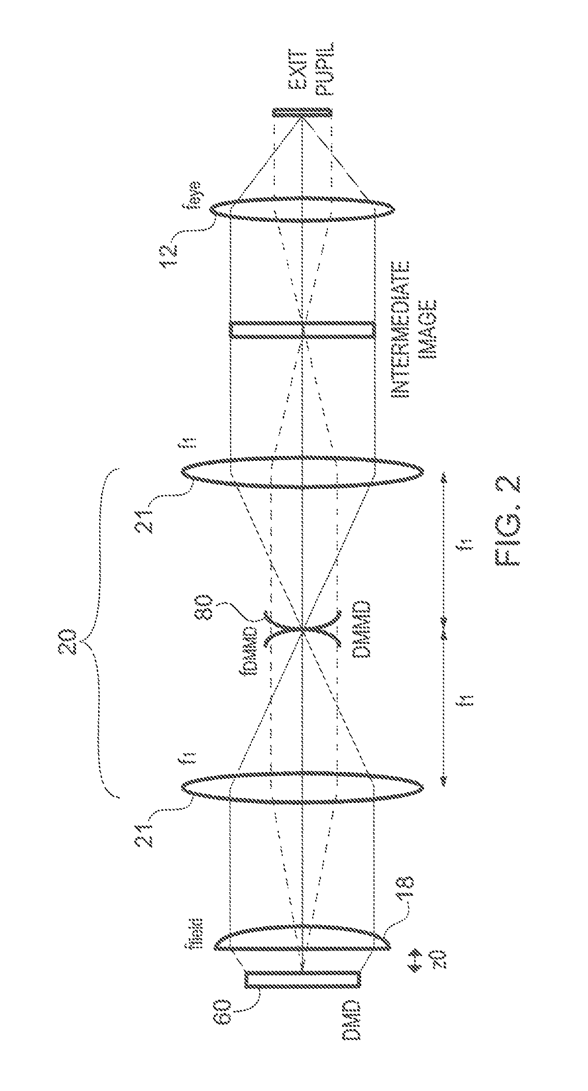
[0030]Referring now to the figures, wherein like elements are numbered alike throughout, in accordance with one aspect of the present invention, FIG. 2 schematically illustrates the first-order unfolded optical path of an exemplary optical system which is particularly suited for providing high imaging quality in depth-fused multi-focal-plane stereoscopic displays with addressable focus cues. FIGS. 3A, 3B schematically illustrate particular designs according to the layout of FIG. 2, with a first optical system 100 having a single field lens 18, FIG. 3A, and an alternative system 200 having a two-element 17, 19 field lens 18, FIG. 3B. (While a single set of optics for a single viewer's eye is illustrated, it is understood that in a final stereoscopic device, two such sets of optics will be provided, one for each eye.)

[0031]A relevant feature of the designs is the inclusion of a relay lens group 20 which relays the image from a microdisplay, such as a digital micro-mirror device (DMD) ...


PUM


Abstract

The present invention relates generally to stereoscopic displays, and more particularly, but not exclusively, to stereoscopic displays with addressable focus cues. A stereoscopic display system with the addressable focus cues, comprises: a microdisplay for providing a virtual image for display to a user; a reflective active optical element configured to provide a variable optical power; a relay lens disposed along an optical path between the microdisplay and the active optical element, the relay lens positioned therebetween such that the microdisplay and the active optical element are disposed at conjugate planes of the relay lens; a beamsplitter disposed along the optical path between the microdisplay and the active optical element at an orientation to receive optical radiation from the active optical element; and a see-through eyepiece comprising a selected surface configured to receive optical radiation from the beamsplitter and reflect the received radiation to an exit pupil of the system to provide a virtual display path, the selected surface also configured to receive optical radiation from a source other than the microdisplay and to transmit such optical radiation to the exit pupil to provide a see-through optical path.

Description

RELATED APPLICATIONS[0001]This present application is a 371 application of International Application No. PCT / US2013 / 065422 filed Oct. 17, 2013, which claims the benefit of priority of U.S. Provisional Application No. 61 / 795,500, filed on Oct. 18, 2012, the entire contents of which application(s) are incorporated herein by reference.GOVERNMENT LICENSE RIGHTS[0002]This invention was made with government support under IIS0915035 awarded by NSF. The government has certain rights in the invention.FIELD OF THE INVENTION[0003]The present invention relates generally to stereoscopic displays, and more particularly, but not exclusively, to stereoscopic displays with addressable focus cues.BACKGROUND OF THE INVENTION[0004]Conventional stereoscopic 3D displays create the illusion of depth based on binocular disparities, rendering 3D scenes from a single pair of 2D perspective images at a fixed distance to the viewer. Therefore conventional stereoscopic displays force an unnatural decoupling of ...

Claims


Application Information

Patent Timeline
Patent Type & Authority Patents(United States)
IPC IPC(8): G02B27/22G02B17/08G02B27/10G02B27/01G02B30/22
CPCG02B27/22G02B17/086G02B27/0101G02B27/0172H04N13/044H04N13/0436G02B27/106G02B2027/0134G02B2027/011G02B2027/0132H04N13/339H04N13/344G02B30/22H04N13/30
Inventor HUA, HONGHU, XINDA
Owner THE ARIZONA BOARD OF REGENTS ON BEHALF OF THE UNIV OF ARIZONA
Why Eureka
Try Eureka