Vehicle seat

a technology for seats and seats, applied in vehicle arrangements, vehicle components, electric/fluid circuits, etc., can solve the problems of increasing the possibility of bracket swinging largely, stem falling off from the mounting hole, and insufficient mounting strength of the bracket, so as to attach the holding member to the seat frame more firmly and effectively, and the effect of more firmly and more effectively

Active Publication Date: 2018-01-30
TOYOTA BOSHOKU KK
View PDF15 Cites 15 Cited by
  • Summary
  • Abstract
  • Description
  • Claims
  • Application Information

AI Technical Summary

Benefits of technology

[0011]In the above aspect of the present invention, the holding member may include a body portion, the mounting portion provided on one side of the body portion, and a hold portion provided on another side of the body portion; and in a state where the mounting portion is fastened to the seat frame, the hold portion may hold the held member and may be disposed away from the seat frame without being fastened to the seat frame. In the above configuration, since mounting stability of the mounting portion is improved, the hold portion can be disposed away from the seat frame without being attached to the seat frame. Thus, the shape and the size of the hold portion can be set appropriately according to the held member regardless of a configuration of the seat frame. That is, in the above configuration, it is possible to attach the holding member to the seat frame more firmly and effectively.
[0012]In the aspect of the present invention, the holding member may be fastened and attached to a surface of the seat frame other than a top surface of the seat frame. In the above configuration, the holding member can be attached to the seat frame while the top surface of the seat frame is kept in a free state. That is, in the above configuration, it is possible to attach the holding member to the seat frame more firmly and more effectively.

Problems solved by technology

Therefore, a mounting strength of the bracket is slightly insufficient.
In the above configuration, for example, when the wire harness is pulled, the bracket may swing, which may cause the stem to fall of from the mounting hole.
In particular, as the bracket becomes heavier due to holding of a plurality of held members such as the wire harness, the possibility that the bracket swings largely and the stem falls off from the mounting hole increases.

Method used


Image

  • Vehicle seat
  • Vehicle seat
  • Vehicle seat

Examples


Embodiment Construction

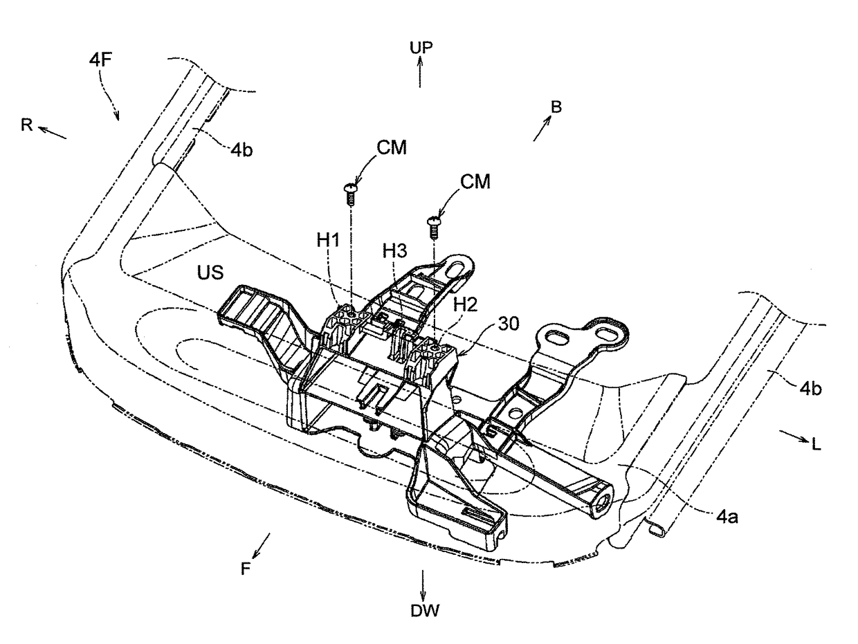
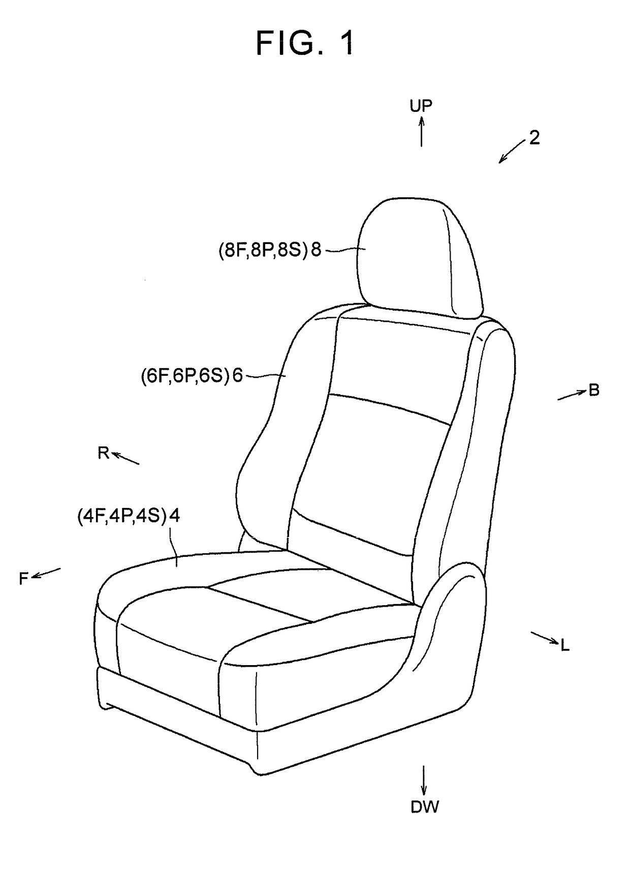
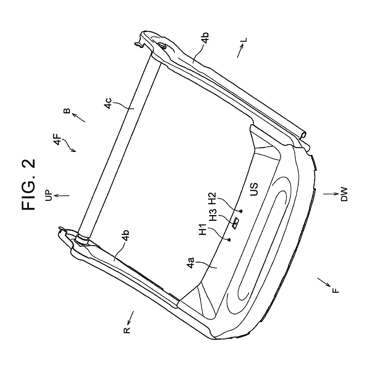
[0026]Hereinafter, an embodiment of the present invention will be described with reference to FIGS. 1 to 11. In each of the drawings, a reference sign F indicates a vehicle-seat front side, a reference sign B indicates a vehicle-seat rear side, a reference sign UP indicates a vehicle-seat upper side, and a reference sign DW indicates a vehicle-seat lower side, a reference sign R indicates a vehicle-seat right side, and a reference sign L indicates a vehicle-seat left side, appropriately. A vehicle seat 2 in FIG. 1 includes a seat cushion 4, a seat back 6, and a headrest 8. The seat components each include: a seat frame (4F, 6F, 8F) serving as a seat framework; a seat pad (4P, 6P, 8P) defining a seat outer shape; and a seat cover (4S, 6S, 8S) covering the seat pad. In the present embodiment, a lower part of the seat back 6 is connected to a rear part of the seat cushion 4 such that the seat back 6 is tiltable (i.e., the seat back 6 is able to be disposed in a standing state and in a ...


PUM


Abstract

A vehicle seat includes a seat frame; and a holding member including a mounting portion that is attached to the seat frame. The holding member is attached to the seat frame via the mounting portion and is disposed and configured to hold a held member; the mounting portion is a tubular part projecting from the holding member toward the seat frame; a fastening member projects from one of the seat frame and the mounting portion and is inserted into the other of the seat frame and the mounting portion such that the holding member is fastened and attached to the seat frame; and the holding member includes five or more flat plate-shaped reinforcing portions projecting from the holding member toward the seat frame, and the five or more reinforcing portions are connected to the mounting portion, and are disposed radially around the mounting portion.

Description

INCORPORATION BY REFERENCE[0001]The disclosure of Japanese Patent Application No. 2015-078562 filed on Apr. 7, 2015 including the specification, drawings and abstract is incorporated herein by reference in its entirety.BACKGROUND OF THE INVENTION[0002]1. Field of the Invention[0003]The present invention relates to a vehicle seat including a seat frame serving as a seat framework, and a holding member that is attached to the seat frame and is able to hold a held member.[0004]2. Description of Related Art[0005]As this kind type of a vehicle seat, a vehicle seat including a seat frame serving as a seat framework, a bracket corresponding to a holding member, and a wire harness corresponding to a held member is well known (see Japanese Patent Application Publication No. 2000-59958 (JP 2000-59958 A)). The wire harness is a cord member disposed inside a seat, and a connector is attached to an intermediate portion of the wire harness. The connector is a substantially cube housing, and a pai...

Claims


Application Information

Patent Timeline
Patent Type & Authority Patents(United States)
IPC IPC(8): B60N2/68B60R16/02B60R16/027B60N2/02B60N2/90
CPCB60R16/0215B60R16/027B60N2/68B60N2002/0264B60N2/0264
Inventor MITA, HIROYUKI
Owner TOYOTA BOSHOKU KK
Why Eureka
Try Eureka