Display apparatus

a technology of display apparatus and slit, which is applied in the direction of television systems, planar/plate-like light guides, instruments, etc., can solve the problems of increased thickness of display apparatus, increased cost, and slit generation at the hanging portion

Inactive Publication Date: 2018-01-30
SAKAI DISPLAY PROD
View PDF18 Cites 0 Cited by
  • Summary
  • Abstract
  • Description
  • Claims
  • Application Information

AI Technical Summary

Benefits of technology

[0023]The present invention has been made in view of the circumstances describe above, and aims to provide a display apparatus in which deflection of optical sheets as well as the occurrence of a slit or the like due to vibration and impact are suppressed while the occurrence of a flaw is suppressed in a member being in contact with the optical sheets, uniform surface luminance and preferable image quality are attained, and the occurrence of a defect is also suppressed.
[0027]Therefore, the display apparatus has uniform surface luminance and preferable image quality while the occurrence of a defect is suppressed.
[0031]Moreover, the support structure for the optical sheet according to the present invention is compact and has a higher degree of freedom in design compared to the case where a projecting part is formed at the bottom part of the chassis, which thus can more preferably narrow the frame.
[0035]Moreover, the optical sheet according to the present invention has a compact support structure.
[0044]According to the display apparatus of the present invention, the occurrence of a deflection as well as a slit or the like due to vibration and impact in the optical sheets is suppressed while the occurrence of a flaw in the member being in contact with the optical sheet is suppressed, which allows the surface luminance to be uniform and the image quality to be preferable, while suppressing the occurrence of a defect. Moreover, the thickness of the display apparatus is not increased.

Problems solved by technology

In the case where the optical sheet is not positioned by the display module, it may flap and make contact with the polarization plate or the like, possibly causing a flaw.
Since the sheet's own weight has become heavier along with the increased size of the display module, the sheet may easily deflect, which causes such a problem that a slit is generated at the hanging portion due to vibration or impact.
Another problem arises in that the thickness of the display apparatus is increased because it is necessary to secure a space for the arrangement of the buffer member 246 in the thickness direction of the display module.
Furthermore, such a configuration has also been a cause for increase in cost.
Moreover, the thickness of the display apparatus is not increased.

Method used


Image

  • Display apparatus
  • Display apparatus
  • Display apparatus

Examples


embodiment 1

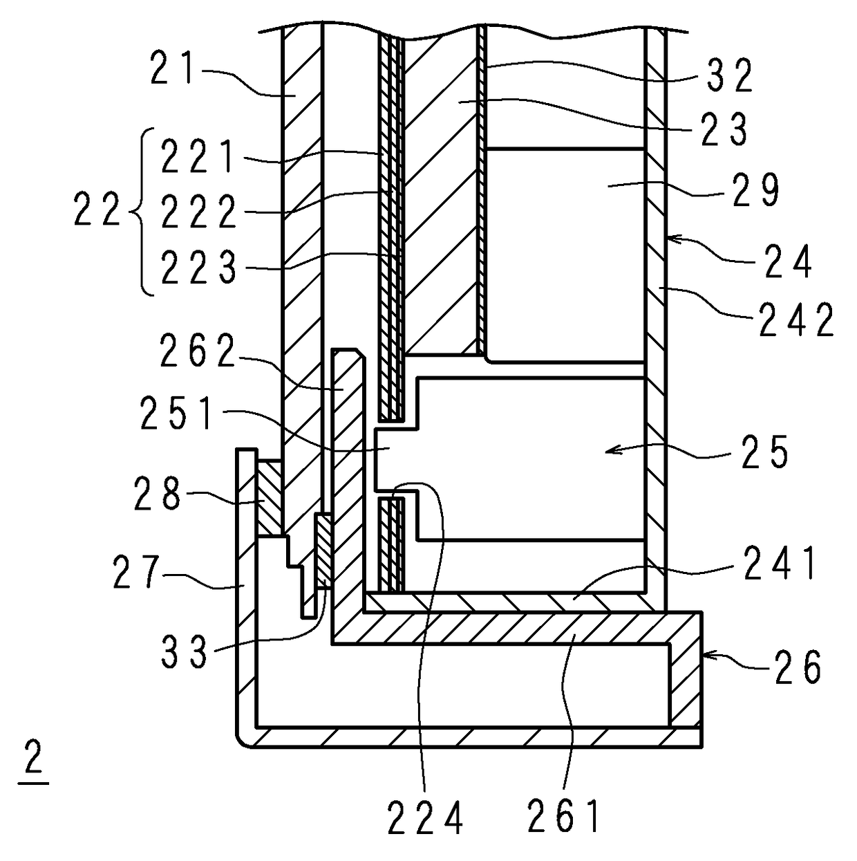
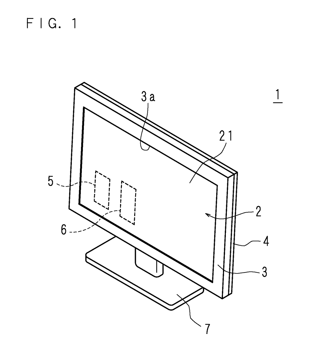
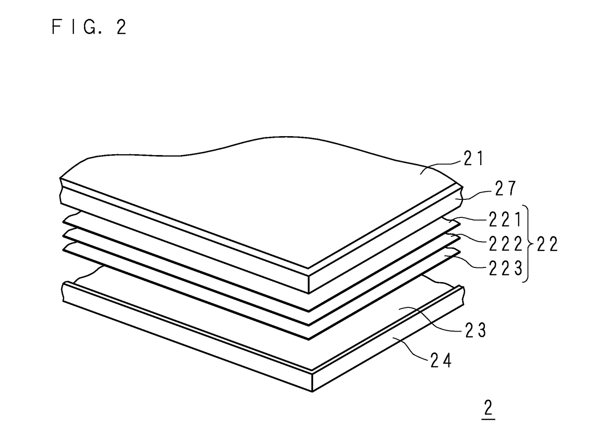
[0062]FIG. 1 is a perspective view of the outer appearance of the front side of a TV receiver 1 according to Embodiment 1 of the present invention; FIG. 2 is a schematic perspective view illustrating a display module 2; FIG. 3 is a schematic front view illustrating an optical sheet group 22 and a chassis 24; and FIG. 4 is a partial vertical section view illustrating a display module 2.

[0063]The TV receiver 1 includes a horizontally-long display module 2 on which a video image is displayed, a tuner 5 receiving broadcast wave from an antenna (not illustrated), and a decoder 6 for decoding encoded broadcast wave. In the TV receiver 1, the decoder 6 decodes broadcast wave received by the tuner 5, and a video image is displayed on the display module 2 based on decoded information. At the lower part of the TV receiver 1, a stand 7 for supporting the TV receiver 1 is provided.

[0064]The display module 2 is accommodated, with a vertical posture, in a front cabinet 3 and a rear cabinet 4 vert...

embodiment 2

[0093]A display module 42 according to Embodiment 2 of the present invention has the same configuration as that of the display module 2 according to Embodiment 1, except that a protrusion 225 is formed at the lower part of the optical sheet group 22.

[0094]FIG. 6 is a schematic front view illustrating an optical sheet group 22 and a chassis 24; FIG. 7 is a partial vertical section view of a display module 42 in a portion of the optical sheet group 22 where a protrusion 225 is not formed; and FIG. 8 is a partial vertical section view of a display module 42 in a portion of the optical sheet group 22 where the protrusion 225 is formed. In FIGS. 6 through 8, the same part as that in FIGS. 3 and 4 is denoted by the same reference code and will not be described in detail.

[0095]At the middle part of the lower side of the optical sheet group 22 in the horizontal direction, a protrusion 225 having a small angled plate-like shape is formed downward, and a latch hole 224 formed in a round hole ...

embodiment 3

[0108]The display module 52 according to Embodiment 3 of the present invention has the same configuration as that of the display module 2 according to Embodiment 1, except that the LED substrate 30 is disposed on the side of the long side surface of the light guide plate 23 and the optical sheet group 22 is supported by the LED substrate 30.

[0109]FIG. 10 is a partial vertical section view illustrating a display module 52 according to Embodiment 3 of the present invention. In FIG. 10, the same part as that in FIG. 4 will be denoted by the same reference code and will not be described in detail.

[0110]The LED substrate 30 is to generate light to be introduced into the light guide plate 23 from a long side surface thereof, and is provided at the side part 241 on the lower side of the chassis 24. The substrate of the LED substrate 30 has a long and narrow rectangular shape, and a plurality of LEDs 31 are mounted on a flat surface of the substrate. The LED substrate 30 extends along the l...


PUM

PropertyMeasurementUnit
luminanceaaaaaaaaaa
surface luminanceaaaaaaaaaa
weightaaaaaaaaaa

Abstract

Provided is a display apparatus in which a deflection of an optical sheet as well as a slit due to vibration and impact are suppressed while a flaw in a member being in contact with the optical sheet is suppressed, uniform surface luminance and preferable image quality are attained, and thus the occurrence of a defect is suppressed.A display module in a TV receiver includes a display panel, an optical sheet group, a light guide plate, a chassis, a panel holding member and a bezel. At the middle part of the lower side portion of the optical sheet group, a latch hole is formed. At a portion of the bottom part of the chassis, which is opposed to the latch hole, is provided with a projecting part formed to have a cylindrical main body and a latch projection continuously formed from the main body with a cylindrical shape having a diameter smaller than that of the main body. The optical sheet group is supported at its lower side portion by a side part on the lower side of the chassis in the state where the latch projection is inserted into the latch hole to position the optical sheet group.

Description

CROSS-REFERENCE TO RELATED APPLICATIONS[0001]This application is the national phase under 35 U.S.C. § 371 of PCT International Application No. PCT / JP2013 / 079219 which has an International filing date of Oct. 29, 2013 and designated the United States of America.BACKGROUND[0002]1. Technical Field[0003]The present invention relates to a display apparatus including a light source, a light guide plate or diffusion plate, an optical sheet and a display panel.[0004]2. Description of Related Art[0005]A thin television receiver such as a liquid-crystal television receiver (hereinafter referred to as TV receiver) generally has a display module (display apparatus: liquid-crystal display module in the case of a liquid-crystal TV receiver), and a substrate for driving the display module. The display module is accommodated vertically in a front cabinet and a rear cabinet that are vertically arranged at the front and back sides. In the case of being a liquid-crystal display module of an edge light...

Claims


Application Information

Patent Timeline
Patent Type & Authority Patents(United States)
IPC IPC(8): F21V8/00G02F1/1333G02F1/1335H04N5/50H04N5/64
CPCG02B6/0088G02B6/0055G02B6/0056G02F1/133308G02F1/133528G02F1/133608H04N5/50G02F1/133606H04N5/64G02F2001/133302G02F2001/133317G02F2201/54G02F1/1335G02F1/133536G02B6/005G02F1/133302G02F1/133317
Inventor SUGIMOTO, ARIMASA
Owner SAKAI DISPLAY PROD
Why Eureka
Try Eureka