Luminaire

a technology of luminaires and light sources, applied in the field of luminaires, can solve the problems of aesthetically disconcerting, unsatisfactory luminaires, and reduced aesthetic appearance of luminaires, and achieve the effects of uniform fixture surface brightness, good color mixing, and great opportunity for color mixing

Active Publication Date: 2016-06-21
KONINK PHILIPS ELECTRONICS NV
View PDF21 Cites 0 Cited by
  • Summary
  • Abstract
  • Description
  • Claims
  • Application Information

AI Technical Summary

Benefits of technology

[0015]By providing two optically coupled light guide layers, one for receiving light emitted by the light sources and the other for emission, greater opportunity for dispersion and color mixing of the light is provided. Thus, the invention provides a luminaire suitable for strip mounting that enables the use of more sparsely distributed light sources, having a uniform fixture surface brightness and good color mixing.
[0016]Furthermore, by providing interface surfaces that are substantially parallel to the longitudinal axis, the light form the light source is coupled into the first light guide layer such that it may be coupled between the first and second light guide layers using total internal reflection alone without any light escaping.
[0030]The luminaire may further comprise a gap in the first light guide layer, the gap extending between two edges of the first light guide layer opposed along a longitudinal axis of the first light guide layer. This structure can be made by folding a sheet of the light guide material, the outer edges of the sheet being brought together adjacent the gap. Again, this results in an integral structure of the first and second light guides and the optical coupler, and is cheap to manufacture.

Problems solved by technology

Modular panel systems typically allow for the rapid construction of floors, walls and ceilings, albeit often at the compromise of reduced aesthetic appearance.
For a number of reasons, such luminaires are not ideal.
Firstly, such luminaires are considered aesthetically displeasing, i.e. obtrusive.
This however can cause glare for an occupant of the office space if the reflected light exits the luminaire under shallow angles to the plane of the modular system.
Glare can be very disturbing in an office environment, as it can obscure the image on a computer monitor and can cause physical discomfort, e.g. headaches or sight problems, to the occupant when being subjected to the glare for a prolonged period of time.
A drawback is that this solution leads to relatively bulky luminaires, which can be considered aesthetically unsatisfactory.
Again, this style of luminaire is relatively bulky and obtrusive.
However, as these luminaires replace tiles in the ceiling, they still disrupt the visual appearance of the suspended ceiling.
If the surface contains high brightness non-uniformities, this can lead to glare and discomfort in the case of direct viewing.
In practice however, a high density closely packed LED distribution will generate too much light for the applications envisioned.
Besides this, cost issues will probably stimulate the use of medium power or even high power LEDs.
It has been found that when spacing the LEDs further apart, the homogeneity rapidly diminishes and becomes unacceptable.
This issue is exacerbated if the fixture is made color-tunable by using a mix of different color LEDs, like for instance warm white and cold white.
The positions of LED sources become clearly visible, having relatively high brightness, and mixing between the colors is very poor.

Method used


Image

  • Luminaire
  • Luminaire
  • Luminaire

Examples


Embodiment Construction

[0050]It should be understood that the figures are merely schematic and are not drawn to scale. It should also be understood that the same reference numerals are used throughout the figures to indicate the same or similar parts.

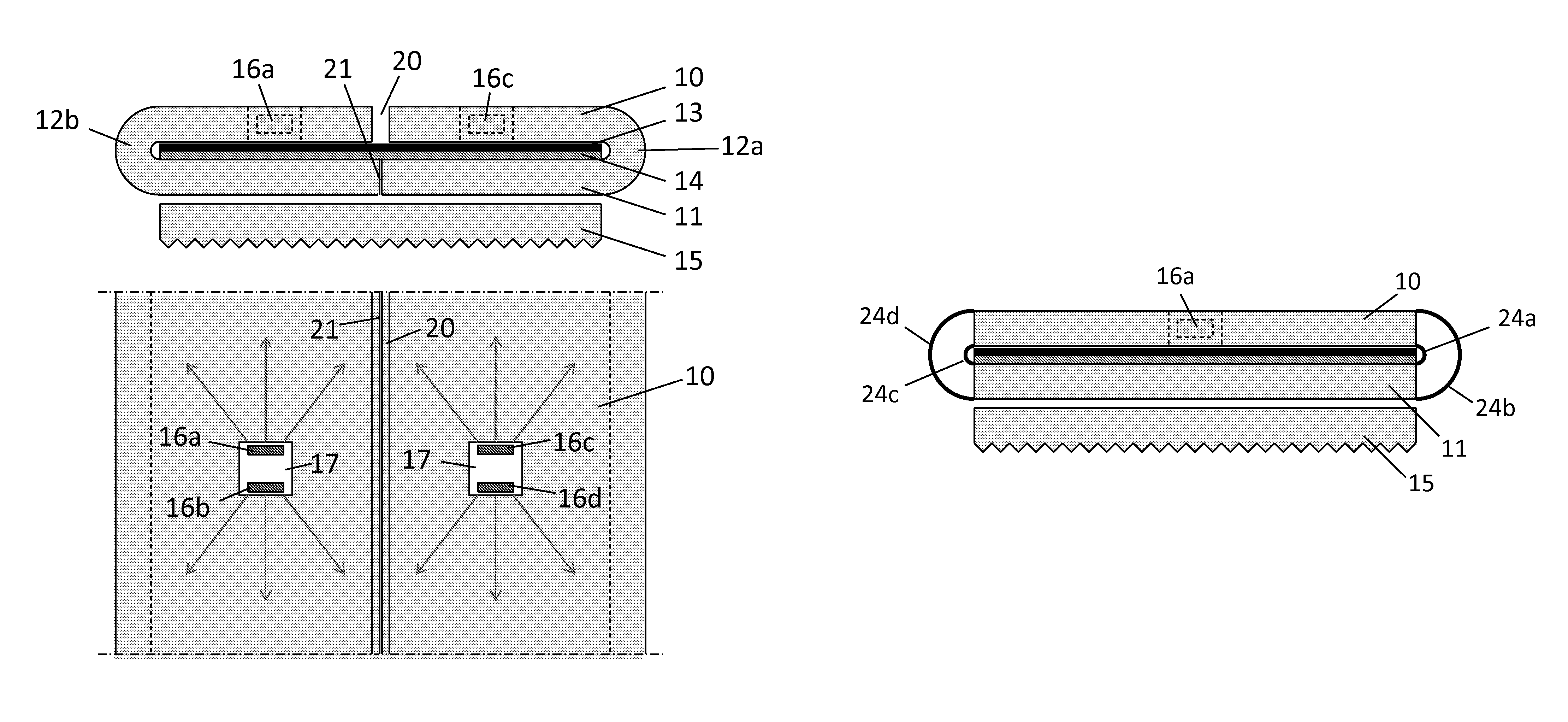
[0051]A first embodiment of the invention is shown in FIGS. 3a and 3b. In this a first or top light guide layer 10 is optically coupled to a second or bottom light guide layer 11 via optical couplers 12a and 12b. The optical couplers 12a and 12b are simply bends to allow the passage of light from the top light guide layer 10 to the bottom light guide layer 11, which lie parallel and spaced apart from each other. The top light guide layer 10, the bottom light guide layer 11 and optical couplers 12a and 12b are contiguous and form an integral structure, which may be manufactured for example by extrusion. They may be made from suitable materials such as PMMA or polycarbonate.

[0052]In the space between the top and bottom light guide layers 10, 11 there are an opa...


PUM


Abstract

The invention relates to a luminaire that enables the use of more sparsely distributed light sources, having a uniform fixture surface brightness and good color mixing. The luminaire comprises first and second light guide layers (10, 11) optically coupled together by at least one optical coupler (12a, 12b), which allows the passage of light from the first (10) to the second light guide layer (11). The luminaire also comprises a plurality of light sources (16a, 16b), each of which being arranged such that light emitted by the light source (16a, 16b) is coupled into the first light guide layer (10) at an interface surface (17)arranged substantially perpendicularly to a longitudinal axis of the first light guide layer (10). The luminaire further comprises a scattering element (14) adapted to cause light to be emitted from an emitting surface of the second light guide layer (11). By providing two optically coupled light guide layers (10, 11), one for receiving light emitted by the light sources (16a, 16b) and the other for emission, greater opportunity for dispersion and color mixing of the light is provided.

Description

FIELD OF THE INVENTION[0001]The present invention relates to luminaires, such as luminaires suitable for mounting in or on a panel support element of a modular panel system. It also relates to a panel support element for a modular panel system comprising such luminaires.BACKGROUND OF THE INVENTION[0002]In construction, modular panel systems are commonly used to reduce build cost and construction time. Modular panel systems typically allow for the rapid construction of floors, walls and ceilings, albeit often at the compromise of reduced aesthetic appearance. A prime example of such a modular panel system is a suspended ceiling, which can be found in most professional environments, such as for example office spaces. A suspended ceiling typically comprises a metal or plastic grid defining rectangular or square recesses, which are filled with tiles to form a continuous ceiling.[0003]In such modular systems, e.g. a suspended ceiling, lighting may be integrated into the system, typically...

Claims


Application Information

Patent Timeline
Patent Type & Authority Patents(United States)
IPC IPC(8): F21V7/04F21V8/00F21S8/06
CPCG02B6/0028G02B6/0053G02B6/0076F21S8/063G02B6/0005G02B6/0021G02B6/0051G02B6/0055G02B6/0068G08B17/06H01H1/00H01H37/52
Inventor DE ZWART, SIEBE TJERKVAN GHELUWE, JOCHEN RENAATMICHIELS, WILHELMUS PETRUS ADRIANUS JOHANNUSVAN BAARDWIJK, MENNOPIJLMAN, FETZEDE HAAS, CORNELIS GERARDUS MARIA
Owner KONINK PHILIPS ELECTRONICS NV
Why Eureka
Try Eureka