
Fluid discharge device

a discharge device and discharge device technology, applied in the direction of measurement devices, electronic circuit testing, instruments, etc., can solve the problems of reducing the volume use of clean dry air and noise generated during operation, and affecting the effect of operation efficiency

Active Publication Date: 2018-02-13
MPI CORP
View PDF11 Cites 0 Cited by
  • Summary
  • Abstract
  • Description
  • Claims
  • Application Information

AI Technical Summary

Benefits of technology

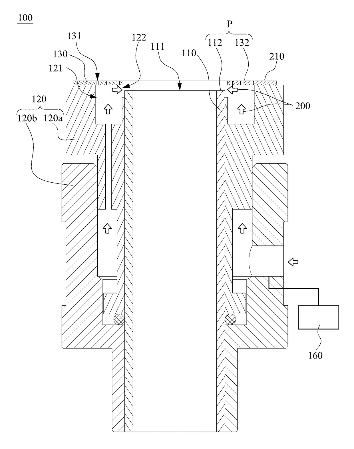
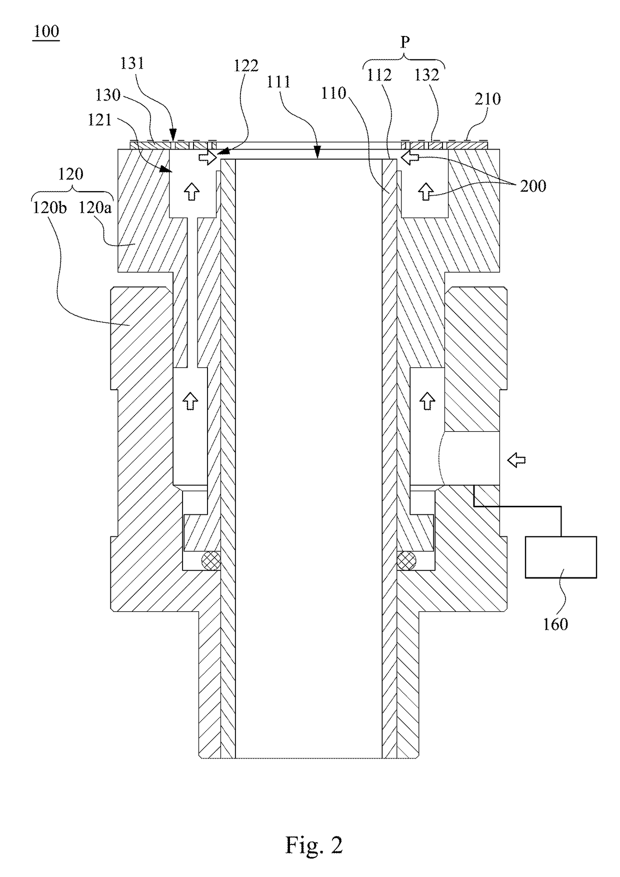
[0008]A technical aspect of the present disclosure provides a fluid discharge device which can block and turn the clean dry air (CDA), such that the clean dry air can effectively pass the low-temperature hardware interface near the discharge port of the low-temperature fluid in contact with the air of a high temperature (room temperature). Apart from effectively reducing the volume use of the clean dry air and the noise generated during operation, the phenomenon of frosting and condensation on the hardware interface near the discharge port is effectively prevented during the discharge of the low-temperature fluid.
[0022]When compared with the prior art, the embodiments of the present disclosure mentioned above have at least the following advantages:
[0023](1) When the clean dry air passes through the outlet, at least part of the clean dry air is blocked by the baffle and is directed to the end surface of the discharge tube, such that the end surface is protected by the clean dry air. Therefore, apart from effectively reducing the volume use of the clean dry air, the phenomenon of frosting and condensation of the moisture on the end surface is effectively prevented.
[0024](2) Since the air layer on the outer surface of the baffle is formed by the clean dry air passing through a plurality of small air holes, the volume use of the clean dry air is effectively reduced.
[0025](3) Since the volume use of the clean dry air is reduced, the noise produced when the clean dry air passing through the air holes is also effectively reduced.

Problems solved by technology

However, since the discharging direction of clean dry air is the same as the discharging direction of the low-temperature fluid, the clean dry air has difficulty forming a protective air layer effectively at the low-temperature hardware interface near the discharge port of the low-temperature fluid.
As a result, if the flow volume of the clean dry air is too small, there will be difficulty preventing the condensation of moisture on the low-temperature hardware interface.
On the other hand, if the flow volume of the clean dry air is increased, most of the clean dry air will be substantially discharged directly into the atmosphere and wasted.
This depletion of a large volume of clean dry air will thus lead to an increase of the operating cost.

Method used


Image

  • Fluid discharge device
  • Fluid discharge device
  • Fluid discharge device

Examples


Embodiment Construction

[0033]Drawings will be used below to disclose a plurality of embodiments of the present disclosure. For the sake of clear illustration, many practical details will be explained together in the description below. However, it is appreciated that the practical details should not be used to limit the claimed scope. In other words, in some embodiments of the present disclosure, the practical details are not essential. Moreover, for the sake of drawing simplification, some customary structures and elements in the drawings will be schematically shown in a simplified way. Wherever possible, the same reference numbers are used in the drawings and the description to refer to the same or like parts.

[0034]Unless otherwise defined, all terms (including technical and scientific terms) used herein have the same meaning as commonly understood by one of ordinary skill in the art to which this disclosure belongs. It will be further understood that terms, such as those defined in commonly used diction...


PUM


Abstract

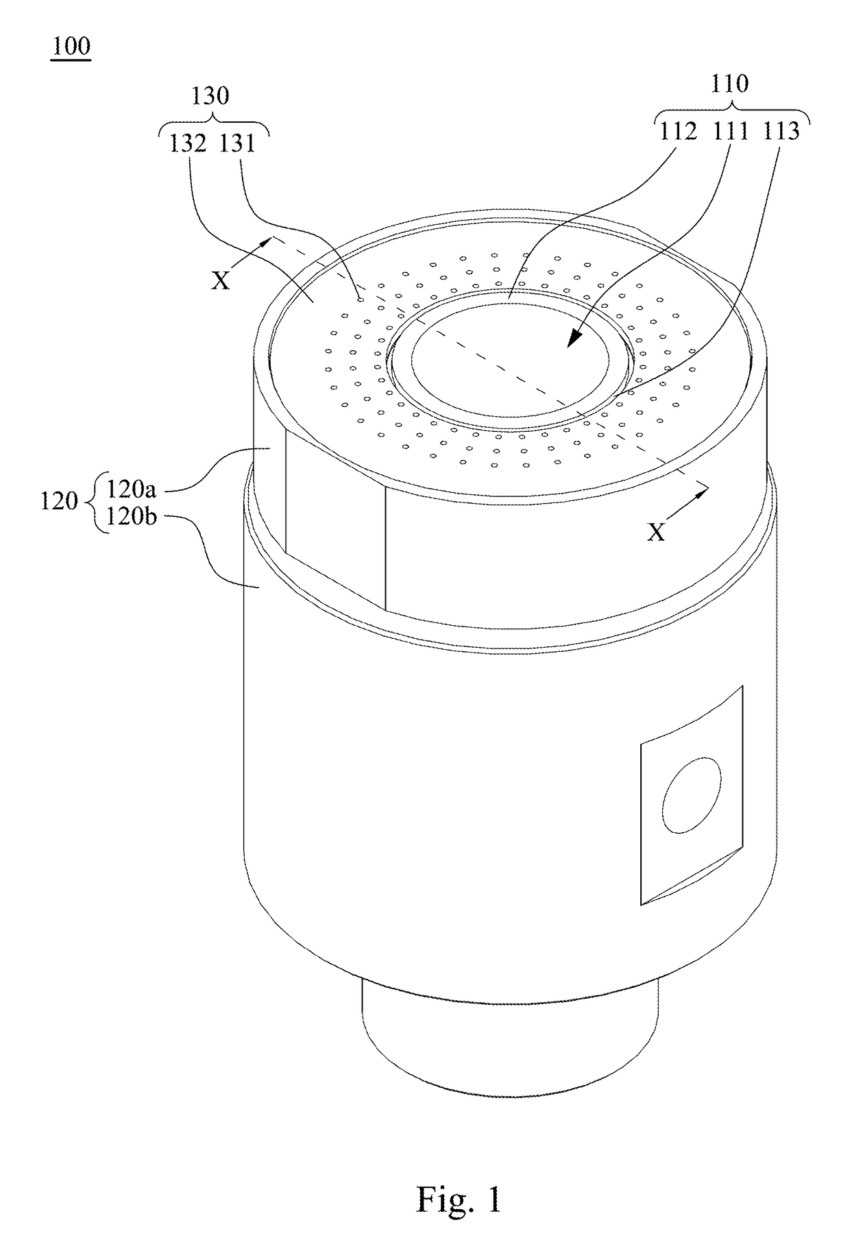
A fluid discharge device includes a discharge tube, an outer tube and at least one baffle. The discharge tube has a discharge port. The discharge tube has an end surface adjacent to the discharge port. The outer tube is sleeved outside the discharge tube. The outer tube has at least one passage. The passage is configured to flow a clean dry air. The passage has an outlet. The baffle is disposed outside the outlet. When the clean dry air passes through the outlet, at least part of the clean dry air is blocked by the baffle and is directed to the end surface of the discharge tube.

Description

RELATED APPLICATIONS[0001]This application claims priority to Taiwan Application Serial Number 103138565, filed Nov. 6, 2014, which is herein incorporated by reference.BACKGROUND[0002]Technical Field[0003]The present disclosure relates to fluid discharge devices. More particularly, the present disclosure relates to gas discharge devices.[0004]Description of Related Art[0005]When a testing environment of a stable temperature is to be established in testing equipment, especially in a low-temperature environment below zero Celsius, one of the approaches is that a low-temperature fluid is continuously supplied to this testing equipment. Naturally, this type of testing equipment requires a fluid discharge device, so as to discharge the used low-temperature fluid into the atmosphere. Thus, the temperature in the testing equipment can be maintained, and the pressure in the testing equipment will not increase.[0006]Traditionally, in order to prevent the discharged low-temperature fluid from...

Claims


Application Information

Patent Timeline
Patent Type & Authority Patents(United States)
IPC IPC(8): B05B7/16B05B7/08G01R31/28
CPCB05B7/16B05B7/0815G01R31/2877
Inventor KRYSTAD, HELGE JACOBLEE, YUEH-YINGCHANG, YING-CHIAO
Owner MPI CORP
Learn More