
Air Conditioning System and Its Oil Return Control Method

A control method and air-conditioning system technology, which is applied in the field of air-conditioning, can solve the problems of reducing unit capacity due to oil return, and achieve the effects of reducing operation risk, avoiding liquid-carrying operation, and effective and reliable oil return

Active Publication Date: 2020-04-28
GREE ELECTRIC APPLIANCES INC
View PDF2 Cites 0 Cited by
  • Summary
  • Abstract
  • Description
  • Claims
  • Application Information

AI Technical Summary

Problems solved by technology

[0005] In order to solve the defect in the prior art that the oil return reduces the capacity of the unit, the present invention proposes an air conditioning system and its oil return control method

Method used


Image

  • Air Conditioning System and Its Oil Return Control Method
  • Air Conditioning System and Its Oil Return Control Method

Examples


Embodiment Construction

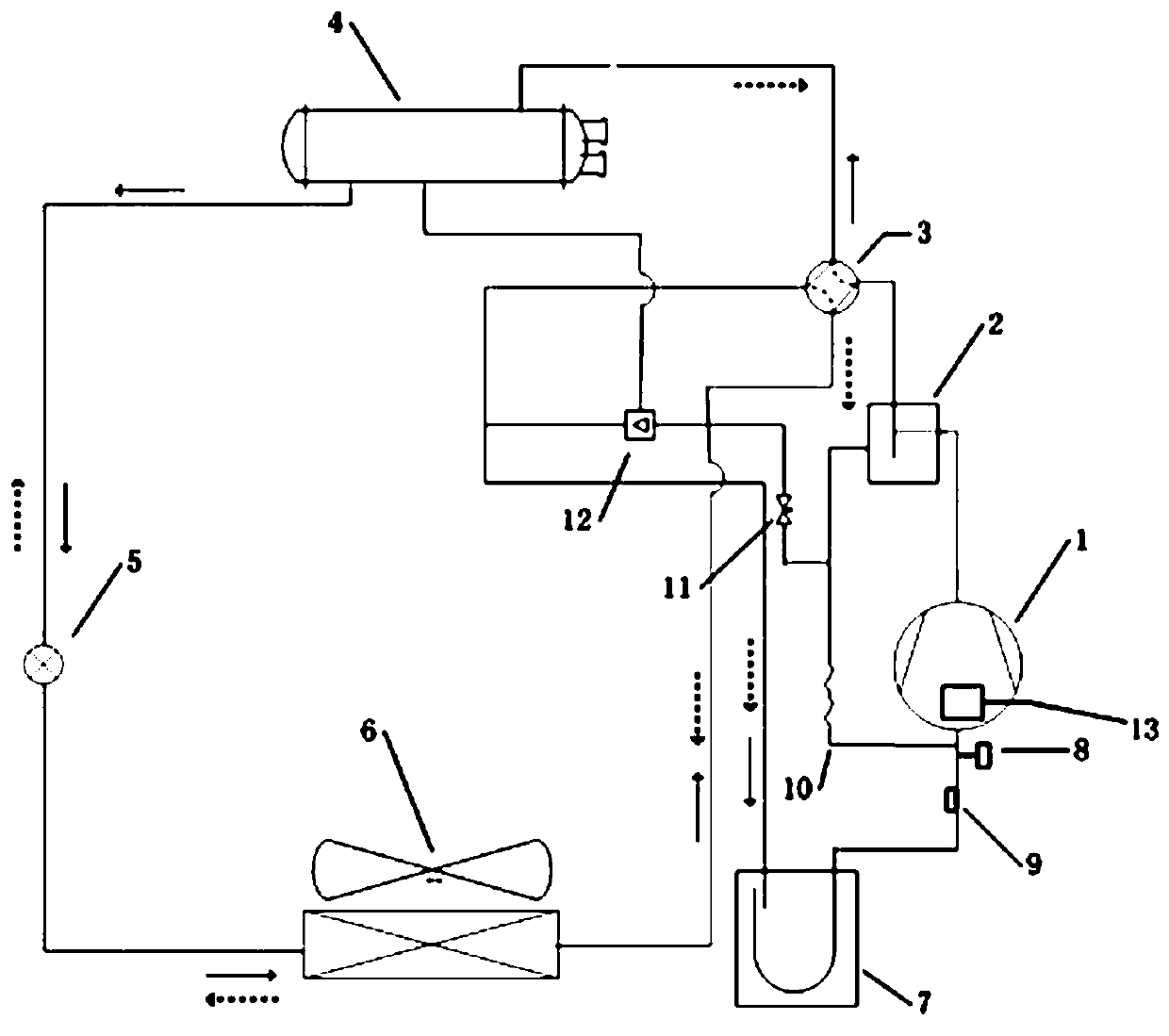
[0030] Such as figure 1 As shown, the air conditioning system proposed by the present invention includes: comprising: a compressor 1, an injector 12 and an oil separator 2, etc., the air inlet of the oil separator 2 is connected to the exhaust port of the compressor 1, and the outlet of the oil separator 2 The oil outlet is set at its bottom position, the ejector 12 is provided with a main inlet, an auxiliary inlet and an output, the main inlet is connected to the oil outlet of the oil separator 2, and the refrigerated oil enters from the auxiliary inlet of the ejector 12 In the ejector 12, the oil in the ejector 12 is sent back to the compressor 1 through the output port.

[0031] Preferably, the air-conditioning system also includes a flooded shell-and-tube heat exchanger 4, the auxiliary introduction end of the ejector 12 is connected to the bottom of the flooded shell-and-tube heat exchanger 4, and the refrigerated oil accumulated in it is sent back to the compressor 1. T...


PUM


Abstract

The invention discloses an air conditioning system and an oil return control method thereof. The air conditioning system comprises a compressor, an ejector and an oil separator, wherein the ejector isused for conveying refrigerant oil back to the compressor, the oil separator is connected with an exhaust port of the compressor, and a main introduction end of the ejector is connected with an oil outlet of the oil separator; and an oil return switch valve is connected between the main introduction end of the ejector and the oil outlet of the oil separator in series, an oil return switch valve is connected with a control device, the control device controls the oil return switch valve according to the operation state of the compressor. The system and the method enable a unit to be kept in good oil returning during operation, and the operation is stable and reliable.

Description

technical field [0001] The invention relates to the technical field of air conditioning, in particular to an air conditioning system and an oil return control method thereof. Background technique [0002] Flooded shell-and-tube heat exchangers are valued by more and more manufacturers because of their large cooling capacity and high energy efficiency ratio. Many chillers use flooded shell-and-tube heat exchangers, especially air-cooled chillers. However, because the tube side of the flooded shell-and-tube heat exchanger uses water and the shell side uses refrigerant, the refrigerant occupies a large space inside the shell and tube, and at the same time the amount of refrigerant is large, the compressor oil is easy to follow the transfer of the refrigerant and accumulate at the bottom of the shell and tube, resulting in system failure. If the amount of oil returned is small, the compressor is prone to lack of oil, which seriously affects the reliability and performance of the...

Claims


Application Information

Patent Timeline
Patent Type & Authority Patents(China)
IPC IPC(8): F25B31/00F25B43/00F25B49/02
Inventor 王传华孙思温祖恒贺秋
Owner GREE ELECTRIC APPLIANCES INC
Learn More