
Dryers for removing solvent from a drug-eluting coating applied to medical devices

a technology of solvent removal and medical devices, applied in the field of drugeluting medical devices, can solve the problems of not being able to satisfactorily meet the needs of certain clinical applications, the improvement of the drug release profile has not been met with success, and the amount or rate of solvent removal is difficult to maintain, so as to maximize the drying efficiency and uniformity of in-process solvent removal, improve product quality, and streamline the manufacturing process

Inactive Publication Date: 2018-03-06
ABBOTT CARDIOVASCULAR
View PDF33 Cites 0 Cited by
  • Summary
  • Abstract
  • Description
  • Claims
  • Application Information

AI Technical Summary

Benefits of technology

[0017]The invention proposes an in-process dryer for maximizing in-process drying efficiency and uniformity for improving the product quality (e.g. coating and its drug release consistency). A dryer and associated process according to the invention can also obviate the need for an oven step which has been relied on to remove residual solvent, thereby streamlining the manufacturing process.
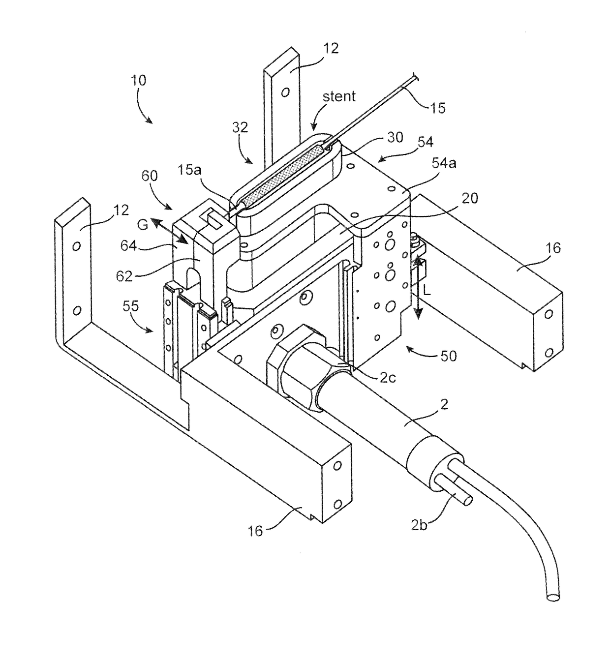
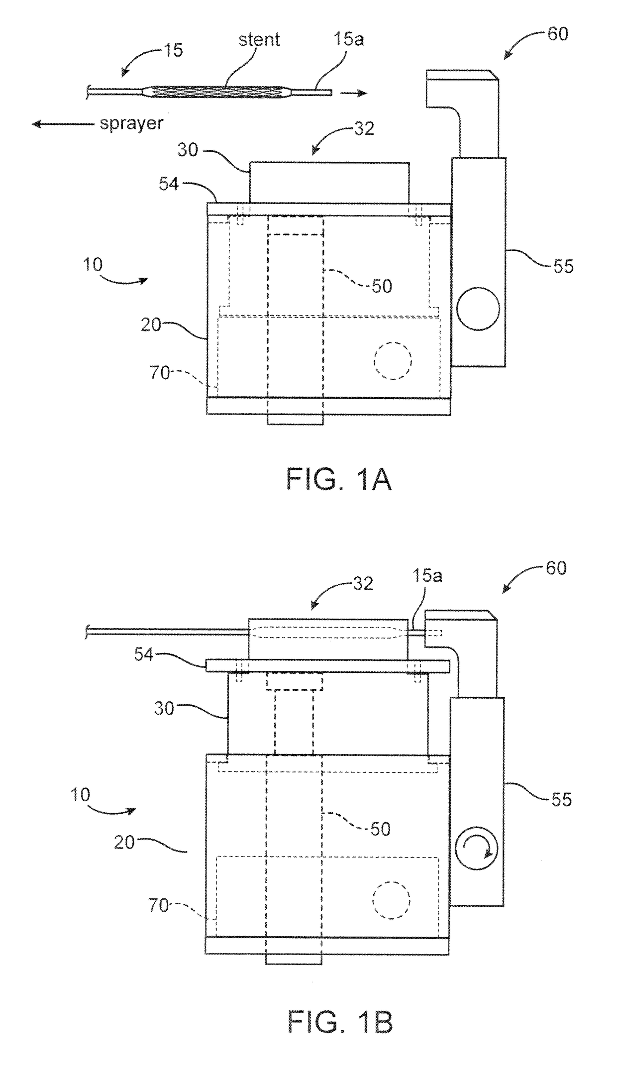
[0018]A dryer nozzle according to the invention has a wider mouth or exit from the plenum than previously proposed stent dryer designs. With this design mean gas velocity at the dryer nozzle is reduced over earlier dryer designs, so that there is less or no influence by the surrounding ambient air and less oscillations of the stent during drying. In a preferred embodiment the dryer is constructed as a telescoping dryer assembly, although other designs are contemplated, e.g., a dryer nozzle that is moved into and out of position as a single unit connected to a flexible gas supply. A shield surrounds the drying region to isolate heated gas from surrounding cooler ambient air. The stent (or scaffold) is disposed within this drying region during the drying step. The dryer nozzle is retractable, which allows clearance for movement of the sent or scaffold between spraying and drying stations. The feature of a retractable dryer nozzle also simplifies drying operations, such as concerns aligning the stent with the mouth or exit.
[0019]A dryer according to the invention addresses alignment issues and uneven drying seen in prior designs by ensuring full coverage and uniform heat application. In addition, the influence of ambient air in the drying operation is effectively minimized or eliminated. Tests have shown that the temperature within the shielded area of the drying region and just above it is at a constant temperature, indicating that no ambient air is drawn into the drying region. Since the hot air within the drying region is at a slightly higher pressure than the surrounding ambient air, ambient air is prevented from being drawn into the drying region. The dryer nozzle includes internal diffusers, e.g., stacked spacer and screen assemblies, to uniformly mix the heated drying gas, resulting in a temperature uniformity of within 1 degree C. across the stent drying area.
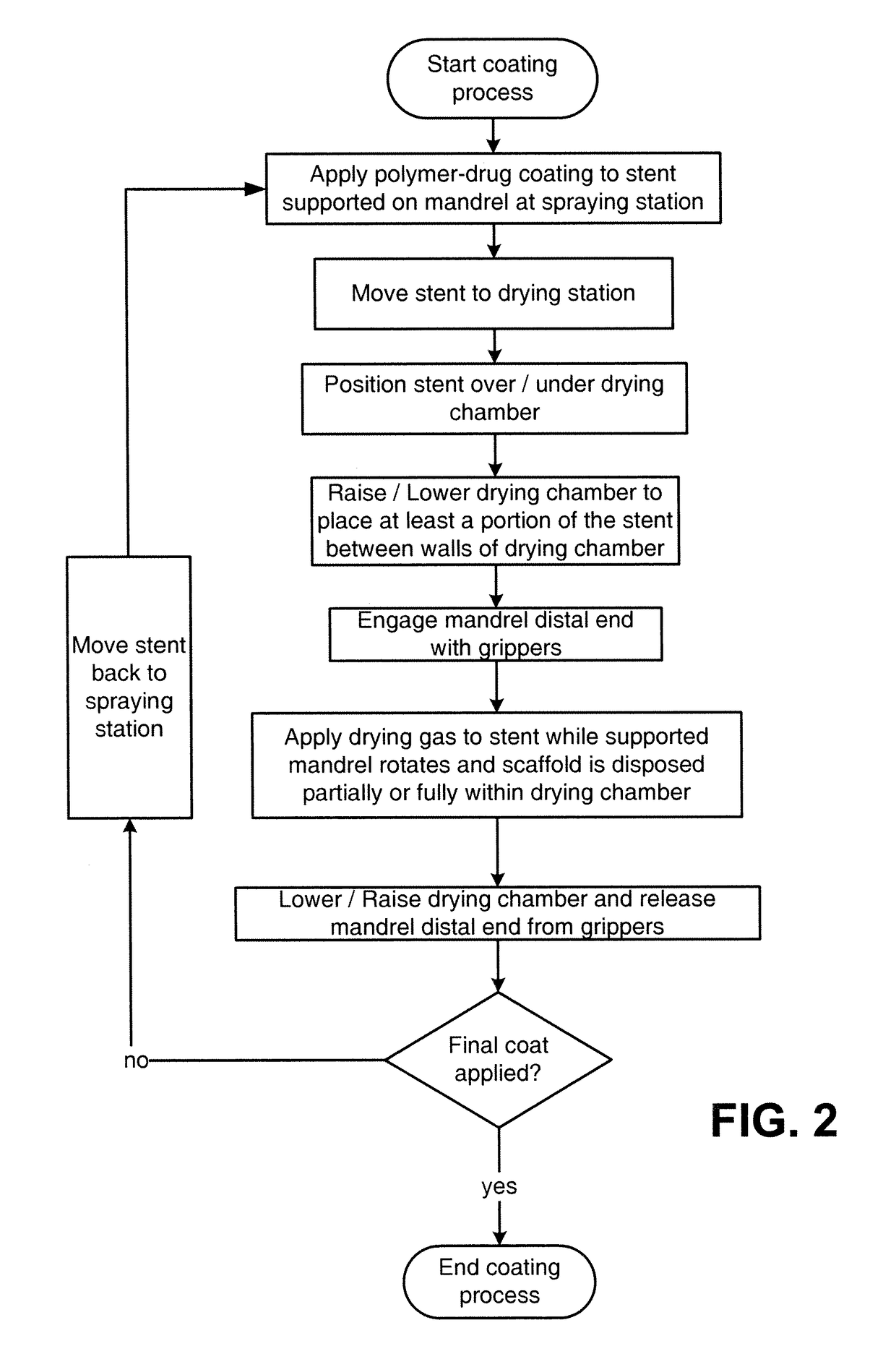
[0020]Accordingly, an inter-pass dryer, according to the invention, that is used in a stent coating process improves on the art by providing an apparatus and method for forming a drug-eluting coating that offers greater control over the release rate for a drug and less undesired interaction between residual solvent and the drug-polymer matrix in the coating. The term “inter-pass drying” means drying, or removing solvent between one, two, three or more spray passes. The weight of material per coat is in some embodiments are very light, about 5% of the total coating weight according to one embodiment. This means, for this particular embodiment, 20 coats are needed to reach 100% of the coating weight.
[0024]According to another aspect of invention, a stent coating system includes a sprayer; a telescoping dryer nozzle; and a linear actuator for moving a stent-supporting mandrel between the telescoping dryer nozzle and the sprayer. The system may further include a rotary actuator for rotating the stent-supporting mandrel to improve consistency and uniformity of solvent removal.INCORPORATION BY REFERENCE

Problems solved by technology

Significant technical challenges exist when developing an effective and versatile coating for a drug eluting medical device, such as a stent.
Previous efforts to produce a more consistent and stable drug release profile have been met with challenges.
However, these improvements have not been able to satisfactorily meet the needs for certain clinical applications, or provide a morphology that can be widely used.
Maintaining control over the amount or rate of solvent removal is, however, challenging unless an applied coating layer is relatively thin.
If the applied layer is too thick the removal of the solvent becomes more difficult to control or predict.
When the solvent is removed from a thick layer, therefore, the potential for undesired interaction among the solvent, polymer and drug, and related problems begin to impair the ability to retain control over the release profile.
For example, if there is excess residual solvent, i.e., solvent not removed between or after a spray cycle, the solvent can induce a plasticizing effect, which can significantly alter the release rate.
If one or more of these parameters are not properly controlled, such that it varies over the thickness or across a surface of a drug-eluting device, then the release profile is affected.
This is because residual solvent on the drug eluting stent may induce adverse biological responses, compromise coating properties, induce drug degradation, and alter release profile.
As explained above, excessive remaining solvent impacts the coating morphology and property.
This can cause variation of the drug release rate and adversely impact the physical properties of the coating.
The design can introduce extensive and interfering mixing of outside air into the gas stream before contacting the stent or scaffold; this mixing of outside air is uncontrolled and causes variation in the temperature across the drying area.
Additionally, the high velocity gas causes the stent to oscillate, which can be problematic for longer-length stents, such as those intended for peripheral vessels.

Method used


Image

  • Dryers for removing solvent from a drug-eluting coating applied to medical devices
  • Dryers for removing solvent from a drug-eluting coating applied to medical devices
  • Dryers for removing solvent from a drug-eluting coating applied to medical devices

Examples


Embodiment Construction

[0036]According to a preferred implementation of the invention, a sprayer and dryer nozzle is used to form a drug-eluting coat on a surface of a stent. A stent is an intravascular prosthesis that is delivered and implanted within a patient's vasculature or other bodily cavities and lumens by a balloon catheter for balloon expandable stents and by a catheter with an outer stent restraining sheath for self expanding stents. The structure of a stent is typically composed of scaffolding, substrate, or base material that includes a pattern or network of interconnecting structural elements often referred to in the art as struts or bar arms. A stent typically has a plurality of cylindrical elements having a radial stiffness and struts connecting the cylindrical elements. Lengthwise the stent is supported mostly by only the flexural rigidity of slender-beam-like linking elements, which give the stent longitudinal flexibility. Examples of the structure and surface topology of medical devices...


PUM


Abstract

A coating device for coating a medical device with a drug-eluting material uses an in-process drying station between coats to improve a drug release profile. The drying station includes a dryer having a telescoping plenum which provides a shield and drying region for the stent or scaffold to reside while a heated gas is passed over the stent / scaffold. The shield and drying region improve efficiency in drying, predictability or drug release rate, uniformity of coating material properties lengthwise over the stent / scaffold and provide a platform that can effectively support stents that are over 40 mm in length.

Description

BACKGROUND OF THE INVENTIONField of the Invention[0001]The present invention relates to drug-eluting medical devices; more particularly, this invention relates to processes for controlling the interaction among polymer, drug and solvent, and the release rate of a drug for drug eluting medical devices.Background of the Invention[0002]Strict pharmacological and good mechanical integrity of a drug eluting medical device are required to assure a controlled drug release. Significant technical challenges exist when developing an effective and versatile coating for a drug eluting medical device, such as a stent.[0003]A coating may be applied by a spray coating process. A drug-polymer composition dissolved in a solvent is applied to the surface of a medical device using this method. The amount of drug-polymer to be applied has been expressed as a target coating weight, which corresponds to the weight of the coating after a substantial amount of the solvent is removed.[0004]Previous efforts ...

Claims


Application Information

Patent Timeline
Patent Type & Authority Patents(United States)
IPC IPC(8): F26B25/06F26B9/00
CPCF26B9/003F26B25/066
Inventor CHEN, YUNG-MINGGILLICK, MATTHEW J.MARTINS, MICHAEL T.PAPP, JOHN E.
Owner ABBOTT CARDIOVASCULAR
Learn More