Method and apparatus in pneumatic materials handling and a waste container/separating device

a technology of waste container/separating device and waste container, which is applied in the direction of bulk conveyors, household applications, refuse collection, etc., can solve the problems of occupying space, affecting the speed needed, and the speed of light waste material from the piping into the waste container/separating device is high, so as to improve the efficiency of the process, efficient fill the container space, and simple waste container/separating device

Active Publication Date: 2018-02-20
MARICAP OY
View PDF64 Cites 7 Cited by
  • Summary
  • Abstract
  • Description
  • Claims
  • Application Information

AI Technical Summary

Benefits of technology

[0016]The solution according to the invention has a number of significant advantages. With the solution according to the invention, it is possible efficiently fill the container space of the waste container / separating devices of pneumatic pipe transport systems for material. This, inter alia, enhances the efficiency of the processes for transporting and storing wastes. The solution according to the invention enables simpler waste container / separating devices than before, in connection with which a separate press device is not needed. The solution according to the invention enables the breakage of waste bags to be avoided better than before when they are fed into the waste container / separating device with a pneumatic pipe transport system for wastes. This has significant advantages, particularly if the sorting of wastes is performed only at the waste station. The solution according to the invention is applicable in connection with very different containers. By using an impact-damping element according to the invention in a waste container / separating device, material can be displaced farther in the piping because the impact-damping element effectively prevents breakage of lighter material allotments, or of the bags or sacks being used in conveying them. By using an impact-damping element to be suspended on the waste container, not only effective impact damping but also a simple structure is achieved. The solution according to the invention also enables efficient emptying of the container, because the impact-damping element moves out of the way of the material to be emptied. According to the invention effective impact damping is achieved with an impact-damping partition arranged on the rear part of the waste container / separating device, on the bottom end of which partition a weight is placed. The solution according to the invention is suited for use in connection with many different types of pneumatic pipe transport systems for material. Also, inter alia, systems using blowing for the conveying of material are feasible, in addition to partial-vacuum systems.

Problems solved by technology

A problem in prior-art combinations of a waste container and separating device, more particularly in horizontal separator containers, is that in them a part of the material, or certain types of materials, remain in the container space loosely packed and thus take up space.
Also the conveying distance in the piping affects the speed needed.
In this case the speed of light waste material from the piping into the waste container / separating device is high, in which case the waste material collides into the container space of the waste container / separating device at a speed that causes the waste bag used in transporting the waste material to break.
This is detrimental particularly in application sites in which different waste allotments are left to be transported from an inlet point along conveying piping into a waste container / separating device and the final sorting of the transported waste bags occurs e.g. only at the waste station to which the waste container / separating device is transported.
It is obvious that the breakage of waste bags hampers sorting and also causes hygiene problems.

Method used


Image

  • Method and apparatus in pneumatic materials handling and a waste container/separating device
  • Method and apparatus in pneumatic materials handling and a waste container/separating device
  • Method and apparatus in pneumatic materials handling and a waste container/separating device

Examples


Embodiment Construction

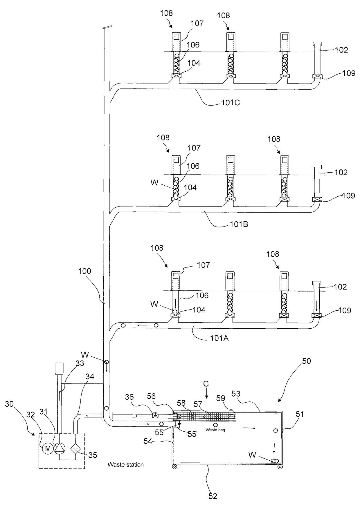
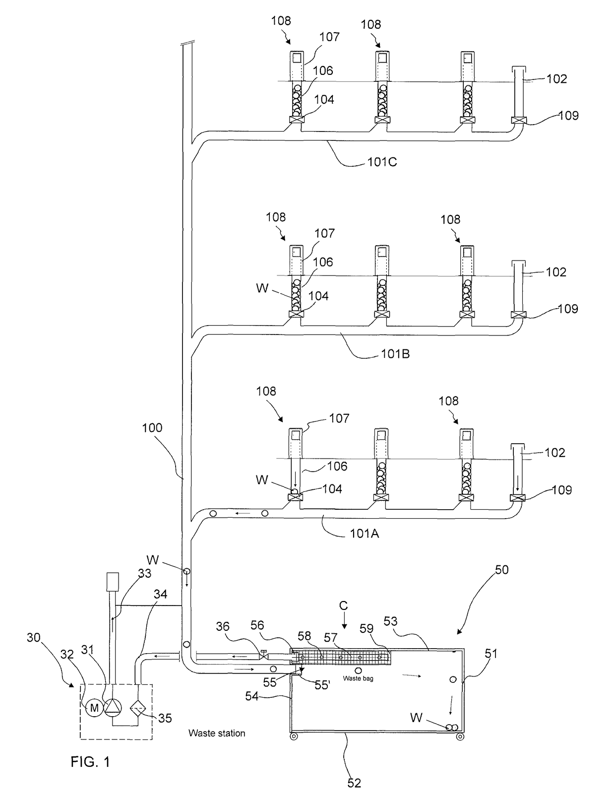
[0029]FIG. 1 presents a diagram of part of a pneumatic material conveying system, which part comprises a material conveying pipe 100, along the side of which at least one, typically many, inlet points 108 are arranged. An inlet point 108 is a feed-in station of material, more particularly of waste material, intended to be transported, from which station the material W, more particularly waste material, such as household waste or recyclable material packed into bags or sacks, intended to be transported is fed into the conveying system. An inlet point 108 can also be a refuse chute, into which material is fed from inlet apertures on different floors of a building. The system can comprise a number of feed-in stations 108, from which the material intended to be transported is fed into conveying piping 100, 101A, 101B, 101C. By opening and closing a shut-off means, such as a valve means 104, that is possibly in connection with an inlet point, material can be conveyed from the inlet point...


PUM


Abstract

Method for filling a waste container / separating device (50) of a pneumatic material conveying system, in which method material is conducted into a material container from a conveying pipe (100) via an inlet aperture (55) and in which method, for bringing about the suction / partial vacuum needed in conveying the material, the suction side of a partial-vacuum source (30) is connected to act in the container space of the waste container / separating device (50) and onwards into the conveying pipe (100). By changing the point at which the suction of the partial-vacuum source acts or the strength of its action in the container space (68) of the waste container / separating device (50), the input direction in the container space of the material (W) being conducted into the container space from the inlet aperture (55) is acted upon. The invention also relates to an apparatus and to a waste container / separating device.

Description

FIELD OF THE INVENTION[0001]The object of the invention is a method for filling a waste container / separating device of a pneumatic material conveying system.[0002]The object of the invention is an apparatus for filling a waste container / separating device of a pneumatic material conveying system, in which a material container is an inlet aperture, to which the material conveying pipe of the conveying system can be connected for conducting the material from the conveying pipe into the container part of the waste container / separating device, and a member is provided for connecting the suction side of a partial-vacuum source, for bringing about the suction / partial vacuum needed in conveying the material, to the container space of the waste container / separating device and onwards into the conveying pipe.[0003]The object of the invention is a waste container / separating device for pneumatic pipe transporting systems for material.[0004]The invention relates generally to material conveying s...

Claims


Application Information

Patent Timeline
Patent Type & Authority Patents(United States)
IPC IPC(8): B65G53/24B65F1/10B65F5/00B65G53/36
CPCB65F1/105B65G53/36B65G53/24B65F5/005B65G53/60
Inventor SUNDHOLM, GORAN
Owner MARICAP OY
Why Eureka
Try Eureka