Apparatus for slicing food products

a technology for food products and slicing blades, applied in metal working apparatuses, nuclear engineering, photometry using electric radiation detectors, etc., can solve the problems of affecting the operation, affecting the quality of food products, so as to prevent contamination

Active Publication Date: 2018-03-13
WEBER MASCHENBAU
View PDF13 Cites 3 Cited by
  • Summary
  • Abstract
  • Description
  • Claims
  • Application Information

AI Technical Summary

Benefits of technology

[0008]An extremely uniform or homogenous illumination of the product end face is achieved on the basis of this configuration while avoiding the total reflections which previously arose, which in particular has a positive effect on the cutting quality and portion quality as well as on the productivity over the total plant over the product throughput. The same brightness is now achieved at every point of the cutting plane since the previously customary overlap of adjacent radiation sources is avoided there. The working speed of the detection device, which in particular comprises a camera system, as well as of the evaluation device is considerably increased. Smaller time windows are sufficient for illuminating the slicing region so that higher cutting blade speeds and / or wider cutting compartments are in particular made possible. Different technical application problems with respect to robustness, precision and handling capability of the cutting apparatus or of the high-performance slicer are thus overcome.
[0034]It must be noted in this respect that the attachment position of the lasers precludes a contamination. The attachment of the lasers therefore expediently takes place in the region of the cutting blade head and thus as closely as possible behind the rear side of the cutting blade.

Problems solved by technology

The installation position of the lamp provided for this purpose, however, frequently causes technical application problems and disadvantages in operation.
However, this now brings about a relatively large drop height which is disadvantageous for the placing down.
In this respect, a shadow falls in the above-disposed surface regions, which can make the evaluation substantially more difficult.

Method used


Image

  • Apparatus for slicing food products
  • Apparatus for slicing food products
  • Apparatus for slicing food products

Examples


Embodiment Construction

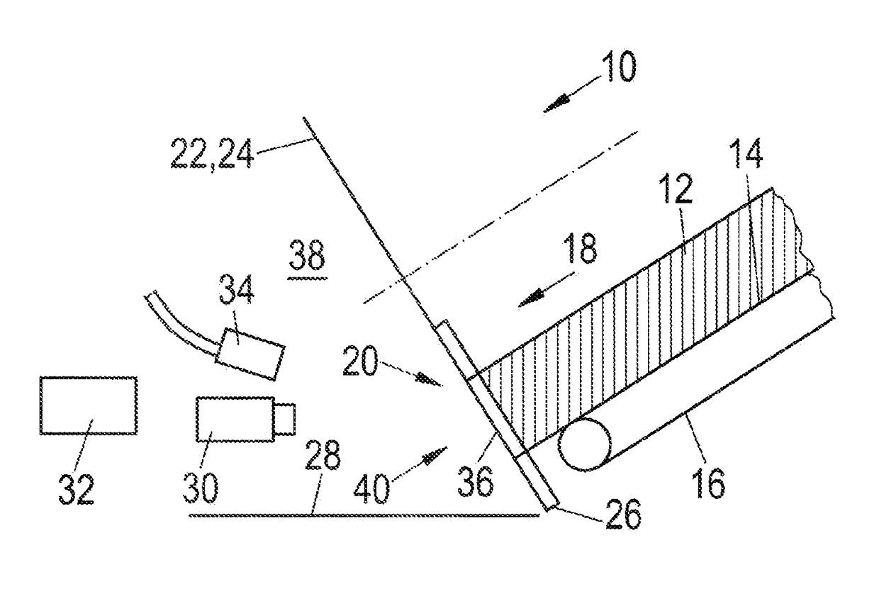
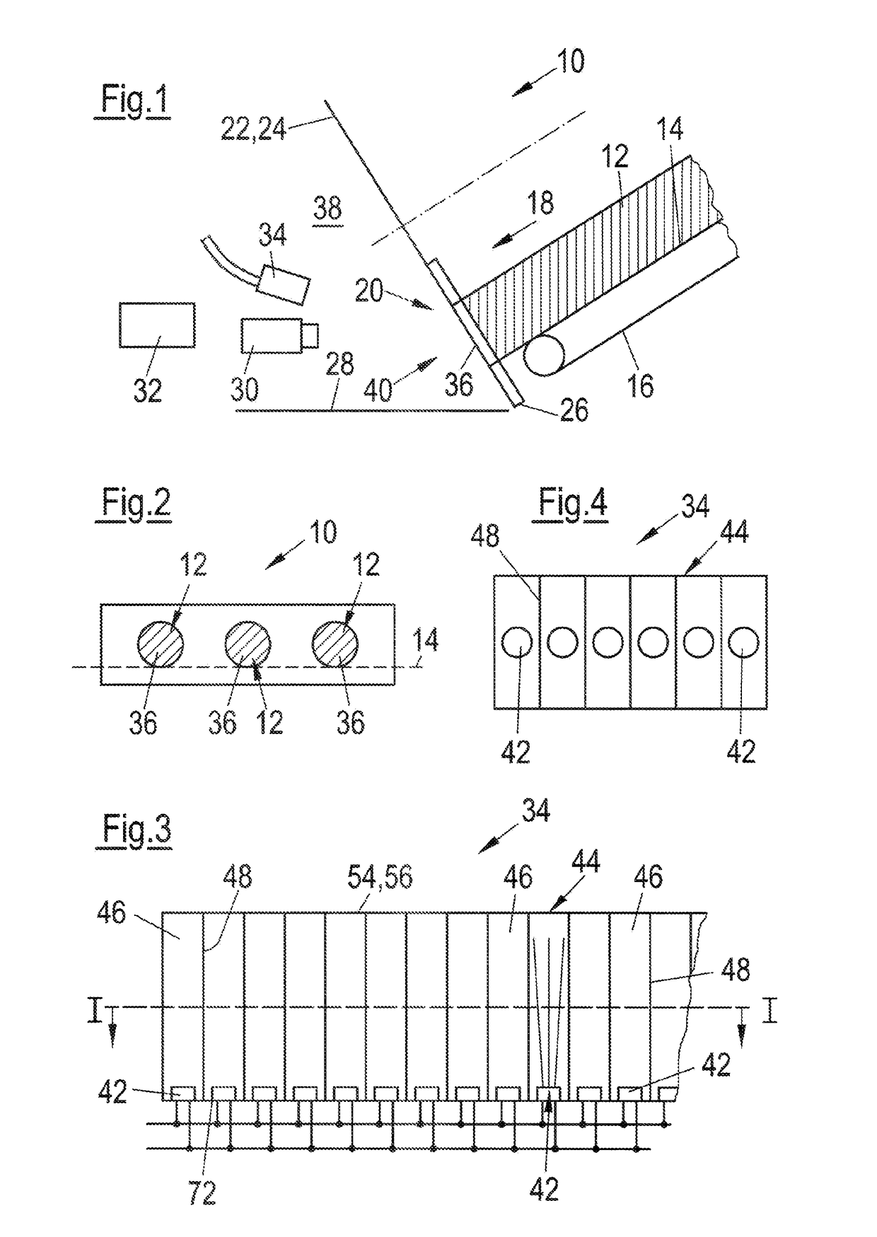
[0046]FIG. 1 shows in a schematic part representation an exemplary embodiment of an apparatus 10 in accordance with the invention for slicing food products 12 (cf. also FIG. 2), which can in particular be a high-performance slicer.

[0047]The cutting apparatus 10 comprises a product feed 16 which defines a feed plane 14 and by means of which the products 12 are fed along the feed plane 14 in a feed direction 18 to a cutting plane 22 disposed in a slicing region 20. A cutting blade 24 moves in the cutting plane 22, in particular in a rotating and / or revolving manner, said cutting blade cooperating with a cutting edge 26 which in particular extends in parallel with the feed plane 14 and perpendicular to the feed direction 18 for cutting off slices from the products 12. A portioning belt 28 or the like can, for example, be provided in the half-space 38 disposed in front of the slicing region 20 for the transporting away of the cut-off slices.

[0048]The cutting apparatus 10 moreover compri...


PUM


Abstract

An apparatus for slicing food products, in particular a high-performance slicer, comprises a product feed which defines a feed plane and by means of which the products are fed along the feed plane in a feed direction to a cutting plane which is disposed in a slicing region and in which a cutting blade moves, in particular in a rotating and / or revolving manner, said cutting blade cooperating with a cutting edge which in particular extends in parallel with the feed plane and perpendicular to the feed direction to cut off slices from the products. The cutting apparatus additionally comprises a detection device for radiation reflected from the slicing region and an evaluation device for evaluating the detected radiation and an illumination device for illuminating the slicing region which is arranged for the at least substantially frontal illumination of the product end face in the half-space disposed in front of the slicing region and above the feed plane and comprises at least one radiation source ad well as a diaphragm arrangement associated therewith which defines a plurality of elongate illumination radiation paths which are optically separate from one another, which each extend in the direction of the slicing region and which are arranged adjacent to one another.

Description

CROSS-REFERENCE TO RELATED APPLICATION[0001]The present patent application claims the benefit of prior filed German Patent Application No. 10 2014 113 424.9, filed on Sep. 17, 2014, the contents of which are incorporated herein by reference in their entirety.FIELD OF THE INVENTION[0002]The invention relates to an apparatus for slicing food products, in particular to a high-performance slicer, having a product feed which defines a feed plane and by means of which the products are fed along the feed plane in a feed direction to a cutting plane which is disposed in a slicing region and in which a cutting blade moves, in particular in a rotating and / or revolving manner, said cutting blade cooperating with a cutting edge which in particular extends in parallel with the feed plane and perpendicular to the feed direction to cut off slices from the products.BACKGROUND OF THE INVENTION[0003]Such apparatus are generally known. In this respect, so-called optical scales are frequently also used...

Claims


Application Information

Patent Timeline
Patent Type & Authority Patents(United States)
IPC IPC(8): B26D7/27G21K5/08G01J1/42B26D5/00B26D7/30
CPCB26D7/27B26D5/007G01J1/42G21K5/08B26D7/30B26D2210/02
Inventor KOSTER, BERNDSTREMEL, JORGBURK, ALEXANDER
Owner WEBER MASCHENBAU
Why Eureka
Try Eureka