Method and apparatus for an adaptive ladar receiver

a receiver and ladar technology, applied in the field of adaptive ladar receiver methods and apparatuses, can solve the problems of large size, large weight, and large power requirements, and the conventional ladar solutions for computer vision problems suffer from high cost, large data bandwidth use, and large data bandwidth

Active Publication Date: 2018-04-03
AEYE INC
View PDF63 Cites 69 Cited by
  • Summary
  • Abstract
  • Description
  • Claims
  • Application Information

AI Technical Summary

Benefits of technology

[0007]As used herein, the term “ladar” refers to and encompasses any of laser radar, laser detection and ranging, and light detection and ranging (“lidar”). Ladar is a technology widely used in connection with computer vision. In an exemplary ladar system, a transmitter that includes a laser source transmits a laser output such as a ladar pulse into a nearby environment. Then, a ladar receiver will receive a reflection of this laser output from an object in the nearby environment, and the ladar receiver will process the received reflection to determine a distance to such an object (range information). Based on this range information, a clearer understanding of the environment's geometry can be obtained by a host processor wishing to compute things such as path planning in obstacle avoidance scenarios, way point determination, etc. However, conventional ladar solutions for computer vision problems suffer from high cost, large size, large weight, and large power requirements as well as large data bandwidth use. The best example of this being vehicle autonomy. These complicating factors have largely limited their effective use to costly applications that require only short ranges of vision, narrow fields-of-view and / or slow revisit rates.
[0008]In an effort to solve these problems, disclosed herein are a number of embodiments for an improved ladar receiver and / or improved ladar transmitter / receiver system. For example, the inventors disclose a number of embodiments for an adaptive ladar receiver and associated method where subsets of pixels in an addressable photodetector array are controllably selected based on the locations of range points targeted by ladar pulses. Further still, the inventors disclose example embodiments where such adaptive control of the photodetector array is augmented to reduce noise (including ladar interference), optimize dynamic range, and mitigate scattering effects, among other features. The inventors show how the receiver can be augmented with various optics in combination with a photodetector array. Through these disclosures, improvements in range precision can be achieved, including expected millimeter scale accuracy for some embodiments. These and other example embodiments are explained in greater detail below.

Problems solved by technology

However, conventional ladar solutions for computer vision problems suffer from high cost, large size, large weight, and large power requirements as well as large data bandwidth use.
These complicating factors have largely limited their effective use to costly applications that require only short ranges of vision, narrow fields-of-view and / or slow revisit rates.

Method used


Image

  • Method and apparatus for an adaptive ladar receiver
  • Method and apparatus for an adaptive ladar receiver
  • Method and apparatus for an adaptive ladar receiver

Examples


Embodiment Construction

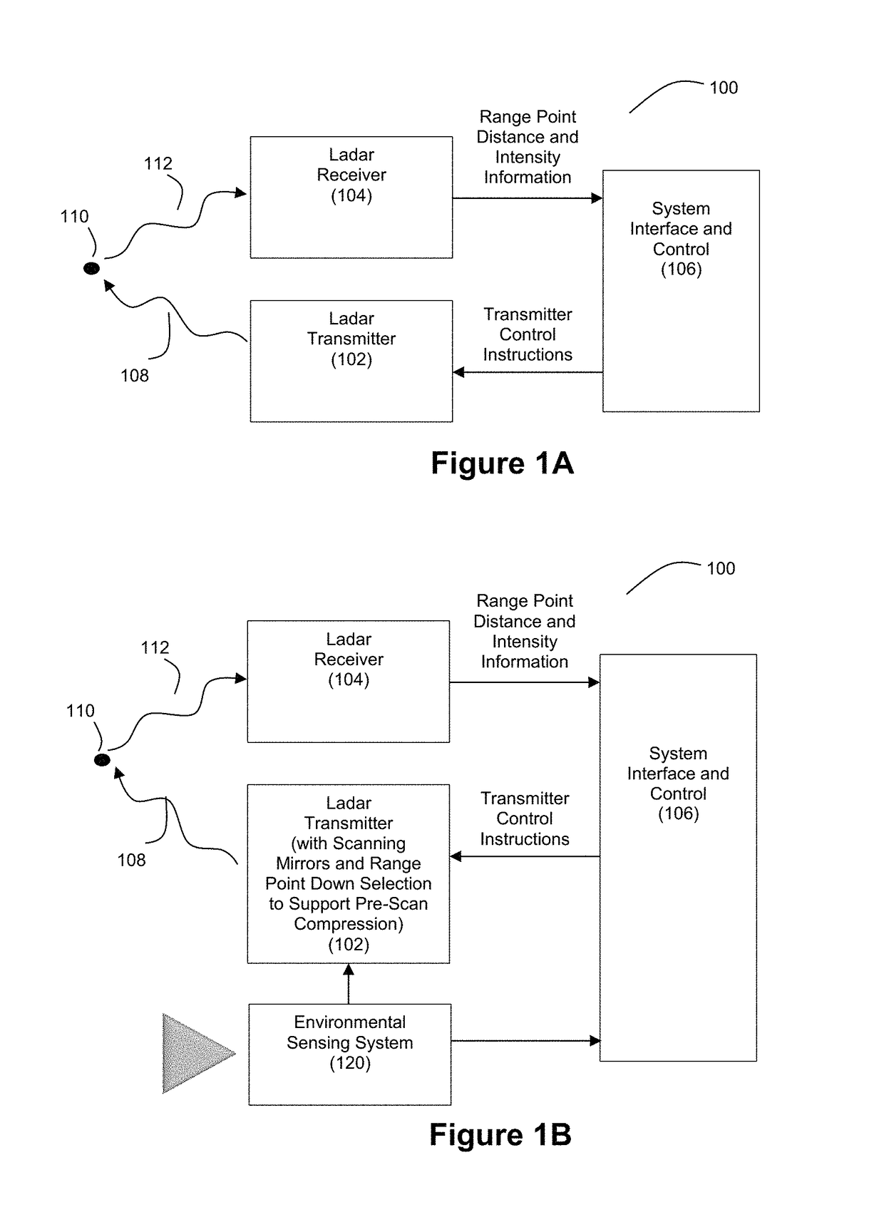
[0035]FIG. 1A illustrates an example embodiment of a ladar transmitter / receiver system 100. The system 100 includes a ladar transmitter 102 and a ladar receiver 104, each in communication with system interface and control 106. The ladar transmitter 102 is configured to transmit a plurality of ladar pulses 108 toward a plurality of range points 110 (for ease of illustration, a single such range point 108 is shown in FIG. 1A). Ladar receiver 104 receives a reflection 112 of this ladar pulse from the range point 110. Ladar receiver 104 is configured to receive and process the reflected ladar pulse 112 to support a determination of range point distance and intensity information. Example embodiments for innovative ladar receivers 104 are described below.

[0036]In an example embodiment, the ladar transmitter 102 can take the form of a ladar transmitter that includes scanning mirrors and uses a range point down selection algorithm to support pre-scan compression (which can be referred herei...


PUM


Abstract

Disclosed herein are various embodiments of an adaptive ladar receiver and associated method whereby the active pixels in a photodetector array used for reception of ladar pulse returns can be adaptively controlled based at least in part on where the ladar pulses were targeted. Additional embodiments disclose improved imaging optics for use by the receiver and further adaptive control techniques for selecting which pixels of the photodetector array are used for sensing incident light.

Description

CROSS-REFERENCE AND PRIORITY CLAIM TO RELATED PATENT APPLICATIONS[0001]This patent application is a continuation-in-part of U.S. patent application Ser. No. 15 / 430,179, filed Feb. 10, 2017, and entitled “Adaptive Ladar Receiving Method”, which claims priority to U.S. provisional patent application 62 / 297,112, filed Feb. 18, 2016, and entitled “Ladar Receiver”, the entire disclosures of each of which are incorporated herein by reference.[0002]This patent application is also a continuation-in-part of U.S. patent application Ser. No. 15 / 430,192, filed Feb. 10, 2017, and entitled “Adaptive Ladar Receiver”, which claims priority to U.S. provisional patent application 62 / 297,112, filed Feb. 18, 2016, and entitled “Ladar Receiver”, the entire disclosures of each of which are incorporated herein by reference.[0003]This patent application is also a continuation-in-part of U.S. patent application Ser. No. 15 / 430,200, filed Feb. 10, 2017, and entitled “Ladar Receiver with Advanced Optics”, whi...

Claims


Application Information

Patent Timeline
Patent Type & Authority Patents(United States)
IPC IPC(8): G01S7/486G01S7/481G01S17/10G01S7/4863G01S7/4865G01S17/931
CPCG01S7/4863G01S17/10G01S7/4868G01S7/4817G01S17/42G01S7/4865G01S7/487G01S7/497G01S17/931
Inventor DUSSAN, LUIS CARLOSSTEINHARDT, ALLANCOOK, DAVID
Owner AEYE INC
Why Eureka
Try Eureka