
Hybrid vehicle and control method for hybrid vehicle

a hybrid vehicle and control method technology, applied in hybrid vehicles, gearing, instruments, etc., can solve problems such as strange or uncomfortable driving, and achieve the effect of reducing the feeling of strangeness

Active Publication Date: 2018-04-17
TOYOTA JIDOSHA KK
View PDF2 Cites 0 Cited by
  • Summary
  • Abstract
  • Description
  • Claims
  • Application Information

AI Technical Summary

Benefits of technology

This approach reduces the likelihood of the driver feeling shift shock by ensuring that virtual and mechanical gear shifts occur in synchronization, thereby minimizing discomfort during gear changes.

Problems solved by technology

However, it is difficult to completely prevent shift shock even in the shift control system as described above, and even a slight shock may cause the driver to feel strange or uncomfortable since the rotational speed of the drive source is substantially constant.

Method used


Image

  • Hybrid vehicle and control method for hybrid vehicle
  • Hybrid vehicle and control method for hybrid vehicle
  • Hybrid vehicle and control method for hybrid vehicle

Examples


Embodiment Construction

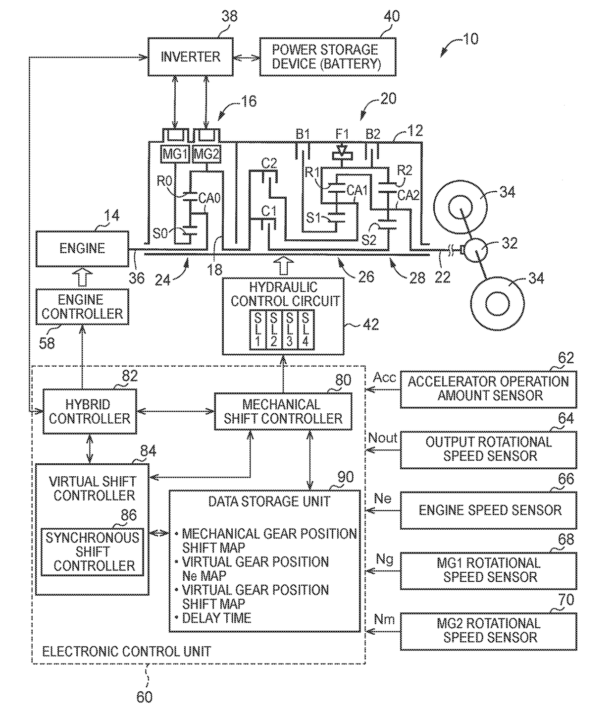
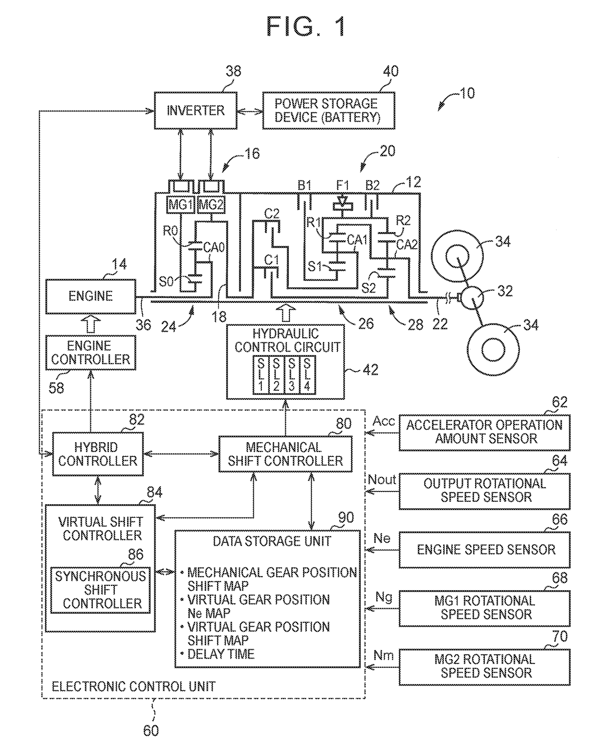
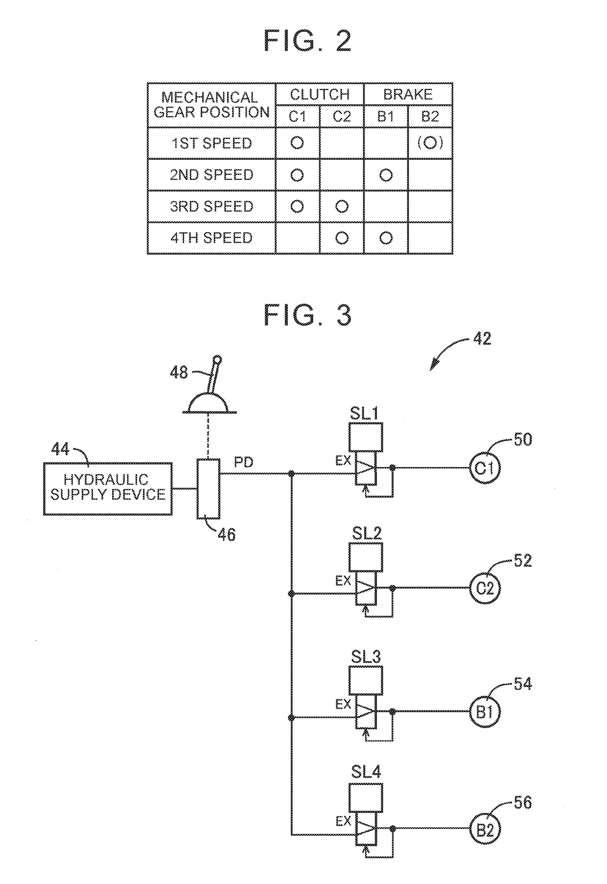
[0022]Next, the configuration of this disclosure will be described. As a drive source of a hybrid vehicle, an engine, such as an internal combustion engine that generates power by burning fuel, an electric motor, or the like, is favorably used. While an electric continuously variable transmission has a differential mechanism, such as a planetary gear unit, it may use a paired-rotor electric motor having an inner rotor and an outer rotor. When the paired-rotor motor is used as the electric continuously variable transmission, the drive source is connected to one of the inner rotor and the outer rotor, and an intermediate transmission member is connected to the other rotor. Like a motor-generator, the paired-rotor motor can selectively deliver power running torque and regenerative torque, and also functions as a rotating machine for differential operation (which will be called “differential rotating machine”). The drive source and the intermediate transmission member are connected to t...


PUM


Abstract

On simultaneous shifts in which shift control of virtual gear positions overlaps shift control of mechanical gear positions, an electronic control unit is configured to delay output of a shift command on the virtual gear position such that shifts of the virtual gear position and the mechanical gear position are performed in synchronization. Therefore, the virtual gear position and the mechanical gear position are shifted in synchronization, irrespective of a difference between the shift response times, and the feeling of strangeness given to the driver due to shift shock, or the like, is suppressed.

Description

INCORPORATION BY REFERENCE[0001]The disclosure of Japanese Patent Application No. 2016-092197 filed on Apr. 30, 2016 including the specification, drawings and abstract is incorporated herein by reference in its entirety.BACKGROUND1. Technical Field[0002]The disclosure relates to a hybrid vehicle, and a control method for the hybrid vehicle.2. Description of Related Art[0003]A vehicle is known which has an electric continuously variable speed change unit that can steplessly change the rotational speed of a drive source through torque control of a differential rotating machine, and transmit resulting rotation to an intermediate transmission member, and a mechanical stepwise variable speed change unit that is disposed between the intermediate transmission member and drive wheels, and can mechanically establish a plurality of gear positions (mechanical gear positions) having different speed ratios of the rotational speed of the intermediate transmission member to the output rotational s...

Claims


Application Information

Patent Timeline
Patent Type & Authority Patents(United States)
IPC IPC(8): B60L9/00F16H61/66B60K6/543B60K6/547B60L11/00G05D1/00B60W20/30F16H37/02F16H61/70F16H3/72B60K6/365
CPCB60W20/30B60K6/365B60K6/543B60K6/547F16H3/728F16H61/66F16H61/702F16H37/022Y10S903/902B60Y2200/92F16H2061/6602F16H61/0403F16H3/66F16H3/727F16H2003/445F16H2200/0043F16H2200/2007F16H2200/2041F16H2200/2066F16H2200/2082F16H37/042B60W2050/0042B60W10/105B60K6/445B60W2510/0638B60W2510/081B60W2540/10B60Y2400/72B60Y2300/182B60Y2400/73Y02T10/62
Inventor BABA, MASAYUKIISOBE, ICHIRO
Owner TOYOTA JIDOSHA KK
Learn More