Lens apparatus and image pickup apparatus having lens apparatus

a technology of lens and image pickup, which is applied in the field of lenses, can solve the problems of significant deterioration of the speed responsiveness of the actuator, performance deterioration, and time-consuming to reach the desired speed, and achieve the effect of reducing the feeling of strangeness of an operation and reducing wear caused

Active Publication Date: 2019-02-19
CANON KK
View PDF12 Cites 0 Cited by
  • Summary
  • Abstract
  • Description
  • Claims
  • Application Information

AI Technical Summary

Benefits of technology

[0010]An object of the present invention is to provide a lens apparatus which enables to reduce a feeling of strangeness to an operation while reducing wear caused in driving of a vibrating motor.
[0012]According to the present invention, it is possible to provide the lens apparatus which enables to reduce the feeling of strangeness to the operation while reducing the wear caused in the driving of the vibrating motor.

Problems solved by technology

For this reason, it has been known that, when the vibrating motor is driven, wear is caused at the contact portion between the vibrating body and the contact body, thereby causing performance deterioration.
However, although the technique disclosed in Japanese Patent Application Laid-Open No. 2009-106043 is effective when driving the actuator at constant speed, it takes time to reach the desired speed.
For this reason, when the driving speed of the actuator frequently changes, speed responsiveness of the actuator significantly deteriorates.
As described above, the vibrating motor is worn out when it is driven.
Therefore, when a lot of driving instructions are given in a short time, namely, when the driving instruction is given frequently, the vibrating motor is resultingly driven frequently, whereby the motor is liable to wear.
However, when such a countermeasure is actually implemented, there is a possibility of bringing a feeling of strangeness in the operation because driving responsiveness of the focus lens to the operation of the demand (a change of a photographed image) deteriorates.

Method used


Image

  • Lens apparatus and image pickup apparatus having lens apparatus
  • Lens apparatus and image pickup apparatus having lens apparatus
  • Lens apparatus and image pickup apparatus having lens apparatus

Examples


embodiment 1

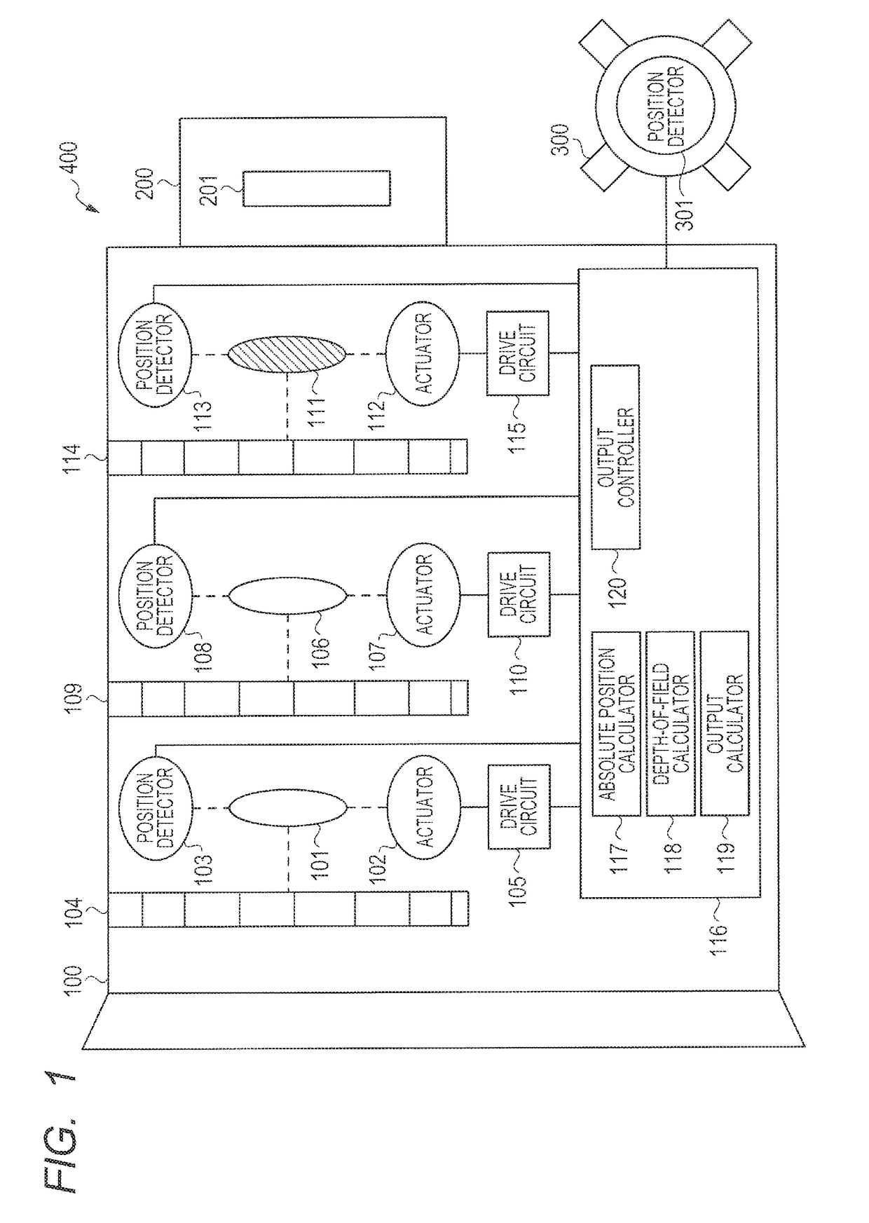
[0023]Hereinafter, a photographing system 400 according to the embodiment 1 of the present invention will be described with reference to FIG. 1. The photographing system 400 is constituted by a lens apparatus 100, an image pickup apparatus 200 and an operating apparatus 300. The image pickup apparatus 200 having an image pickup element 201 is connected to the lens apparatus 100, so that the image pickup apparatus receives light from the lens apparatus 100 by the image pickup element 201 and photoelectrically converts the received light. Besides, the operating apparatus 300 is connected to the lens apparatus 100.

[0024]Hereinafter, the constitution of the lens apparatus 100 will be described. The lens apparatus 100 is constituted by an optical system having optical adjusting members such as a focus lens 101, a zoom lens 106 and a stop 111. Each of the optical adjusting members comprises an actuator, a position detector and an operating unit. The focus lens 101 is the member for displa...

embodiment 2

[0049]Hereinafter, the embodiment 2 of the present invention will be described with reference to FIGS. 6 to 7B.

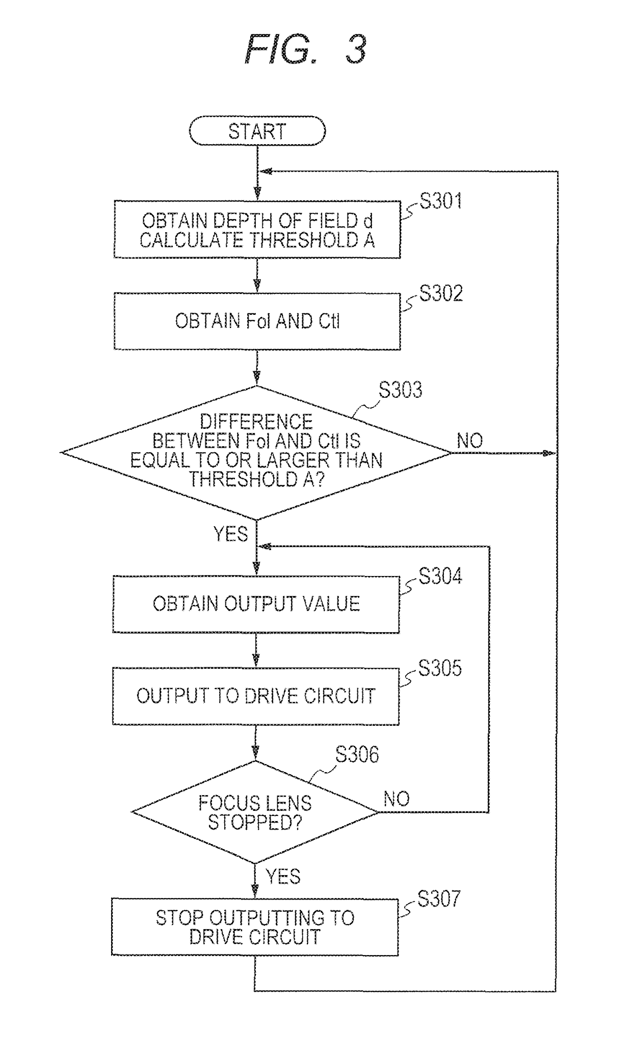
[0050]In the embodiment 1, when the difference between the current position of the focus lens 101 and the instruction position exceeds the predetermined threshold A, the output to the drive circuit 105 is performed, thereby driving the focus lens 101. Further, when it is decided that the focus lens 101 is stopped, also the output to the drive circuit 105 is stopped. In the present embodiment, operation / no operation from the operating apparatus is decided. Then, when no operation is decided (that is, it is decided that the operating apparatus is not operated), the focus lens 101 is driven irrespective of whether or not the difference between the current position and the instruction position is equal to or larger than the threshold A.

[0051]The constitution of the photographing system 400 in the present embodiment is the same as that in the embodiment 1, the description thereo...


PUM


Abstract

A lens apparatus comprises an optical system including a focus lens, a vibrating motor for driving the focus lens in an optical axis direction, a detector for detecting a position of the focus lens in the optical axis direction, an operating unit for inputting a position instruction for the focus lens, and a controller for, on the basis of the position instruction and a state of the optical system, switching between a case of controlling the motor by using an instruction value which is obtained on the basis of the position of the focus lens obtained from the detector and the position instruction obtained from the operating unit and a case of not controlling the motor by using the instruction value.

Description

BACKGROUND OF THE INVENTION[0001]Field of the Invention[0002]The present invention relates to a lens apparatus. In particular, the present invention relates to the lens apparatus which controls driving of a focus lens by a vibrating motor, and to an image pickup apparatus which has the lens apparatus.[0003]Description of the Related Art[0004]As for a lens apparatus used in photography, videography and the like, the type which adopts a vibrating motor as an actuator for a focus lens is known. The feature of the vibrating motor is different from the feature of a magnetic motor in the points of being able to obtain large torque even in low-speed rotation, having high holding force during a stop of the motor, being unaffected by magnetism, and the like.[0005]The vibrating motor is constituted by a vibrating body which is formed by a metallic elastic member having a mechanical-electrical energy convertor (piezoelectric device, electrostrictive element) joined or the like, and a contact b...

Claims


Application Information

Patent Timeline
Patent Type & Authority Patents(United States)
IPC IPC(8): G02B7/02G02B7/08G02B7/10G03B3/10
CPCG02B7/08G03B3/10G02B7/102
Inventor MAKITA, KEISUKE
Owner CANON KK
Why Eureka
Try Eureka