Liquid ejection head

a liquid ejection and head technology, applied in the field of liquid ejection heads, can solve the problems of increasing the size of the device (e.g., the printer or the head) as a whole, undesirably becoming difficult to dispose of tab film, and the tab film being difficult to pass between the adjacent two head units, so as to reduce the size of the head unit

Active Publication Date: 2018-05-22
BROTHER KOGYO KK
View PDF19 Cites 5 Cited by
  • Summary
  • Abstract
  • Description
  • Claims
  • Application Information

AI Technical Summary

Benefits of technology

[0005]An aspect of the disclosure relates to a liquid ejection head which enables the wiring member to be disposed so as to avoid adjacent head units while the drive circuit is mounted on the wiring member for reducing a size of the head unit.

Problems solved by technology

When the drive circuit is incorporated in the head unit, the head unit tends to be large-sized, resulting in an increase in the size of a device (e.g., printer or head) as a whole.
If the TAB film has a large width, it undesirably becomes difficult for the TAB film to pass between the adjacent two head units.
That is, it becomes difficult to dispose the TAB film so as to avoid the adjacent two head units.

Method used


Image

  • Liquid ejection head
  • Liquid ejection head
  • Liquid ejection head

Examples


Embodiment Construction

[0021]There will be described one embodiment.

Overall Structure of Printer

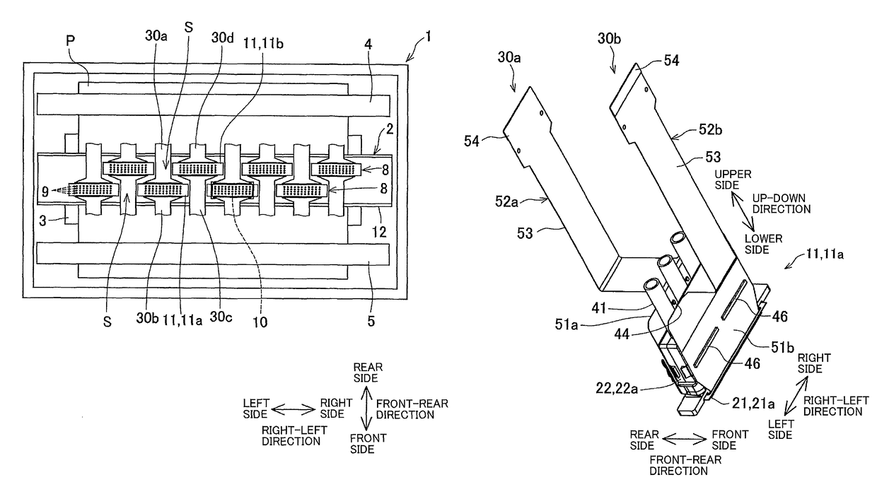
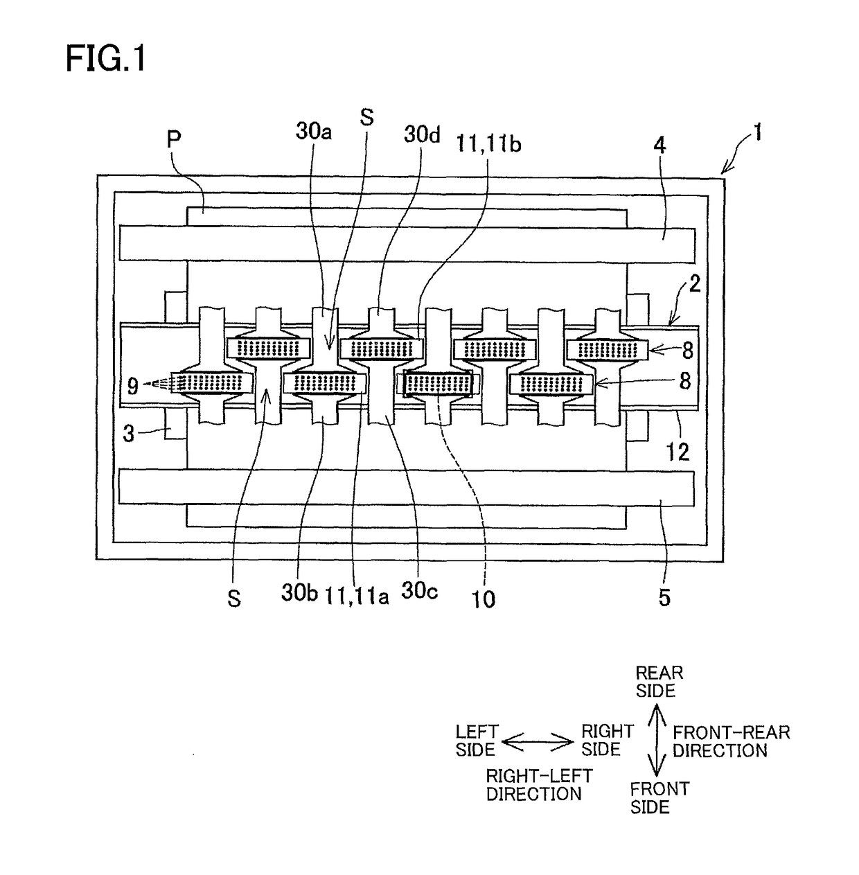
[0022]As shown in FIG. 1, a printer 1 includes an ink-jet head 2 (as one example of “liquid ejection head”), a platen 3, and conveyance rollers 4, 5. As shown in FIG. 1, a direction parallel to a direction in which a recording sheet P is conveyed in the printer 1 is defined as a front-rear direction, and a direction parallel to a conveyance surface of the recording sheet P and perpendicular to the front-rear direction is defined as a right-left direction. Further, as shown in FIG. 1, a front side and a rear side are defined with respect to the front-rear direction, and a right side and a left side are defined with respect to the right-left direction. Each of the front-rear direction and the right-left direction is a horizontal direction orthogonal to an up-down direction.

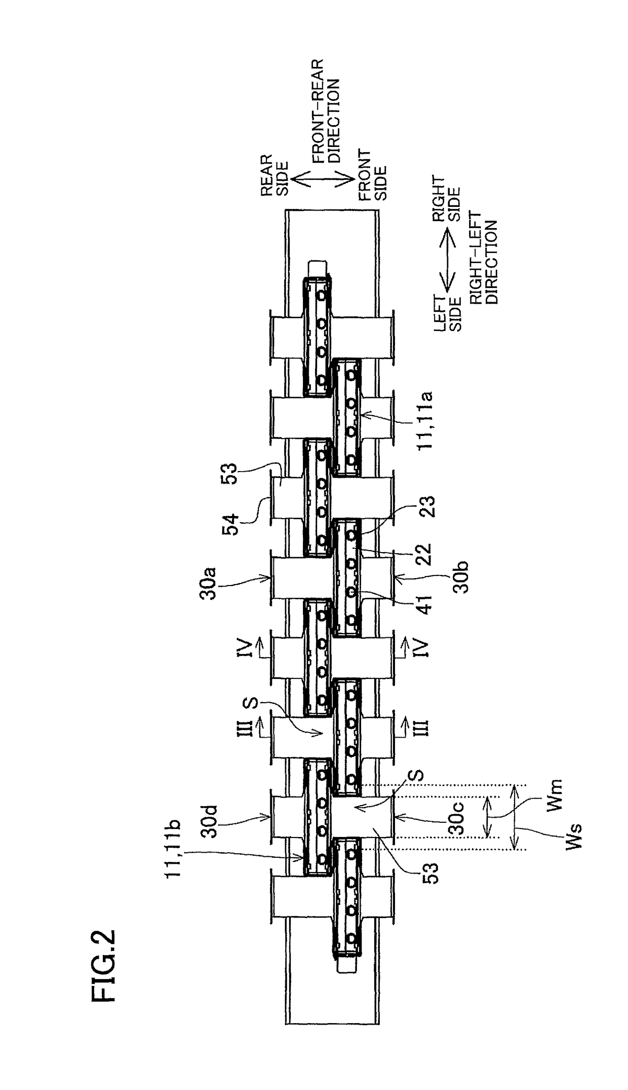
[0023]The ink-jet head 2 is the so-called line head extending over an entire dimension of the recording sheet P in the right-left direction. A...


PUM


Abstract

A liquid ejection head, including: a first head unit; a second head unit shifted with respect to the first head unit in both of a first direction in which nozzles of the head units are arranged and a second direction orthogonal to the first direction and disposed so as to overlap the first head unit in the second direction; and a first wiring member having flexibility and drawn from the second head unit in the second direction toward the first head unit, wherein the first wiring member includes a large-width portion on which a drive circuit is mounted and a small-width portion having a width in the first direction smaller than a width of the large-width portion in the first direction, and wherein the small-width portion passes through a space existing next to the first head unit in the first direction and extends in the second direction.

Description

CROSS REFERENCE TO RELATED APPLICATION[0001]The present application claims priority from Japanese Patent Application No. 2016-130334, which was filed on Jun. 30, 2016, the disclosure of which is herein incorporated by reference in its entirety.BACKGROUNDTechnical Field[0002]The following disclosure relates to a liquid ejection head configured to eject a liquid.Description of Related Art[0003]There is known an ink-jet printer in which head-units (head modules) are arranged in two rows which are adjacent to each other. In the printer, the head units of one row and the head units of another row are shifted relative to each other such that opposite end portions of one head unit in one row overlap respectively end portions of corresponding adjacent two head units in another row. In the known printer, a TAB film is connected to each head unit. For permitting the TAB films connected to the head units in the two rows to be drawn toward the same side of the printer, the TAB film connected to...

Claims


Application Information

Patent Timeline
Patent Type & Authority Patents(United States)
IPC IPC(8): B41J2/14
CPCB41J2/1433B41J2/155B41J2002/14491B41J2202/20
Inventor HAYASHI, HIDEKISUGIURA, KEITAMIZUNO, TAISUKE
Owner BROTHER KOGYO KK
Why Eureka
Try Eureka