

Liquid ejecting head, liquid ejecting head unit and liquid ejecting apparatus
a liquid ejecting head and liquid ejecting technology, applied in the direction of printing, inking apparatus, etc., can solve the problems of increasing manufacturing costs, difficult parts processing and assembly, and inability to obtain excellent ink dischargeability, so as to reduce manufacturing costs and size
- Summary
- Abstract
- Description
- Claims
- Application Information
AI Technical Summary
Benefits of technology
Problems solved by technology
Method used
Image

Examples
first embodiment
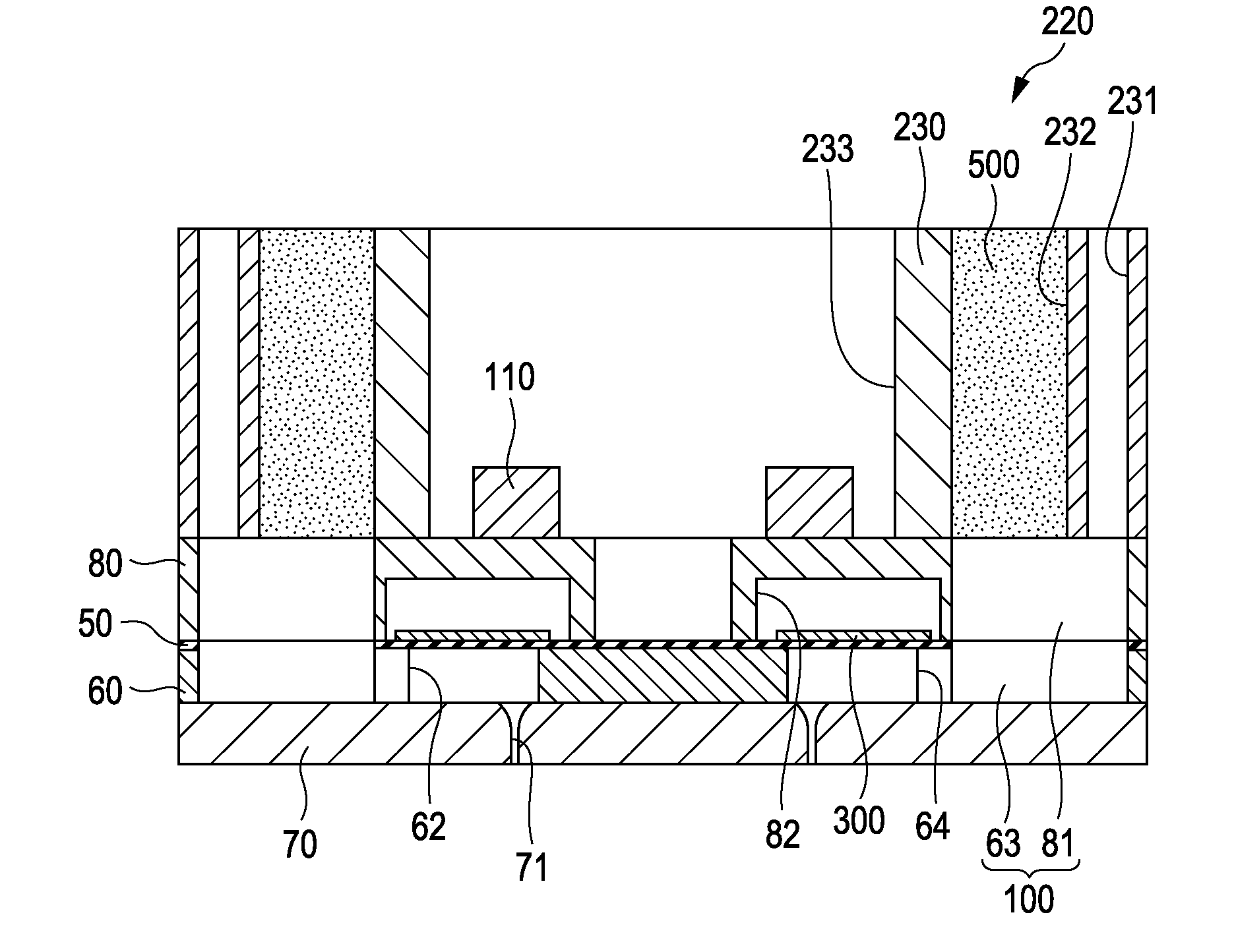
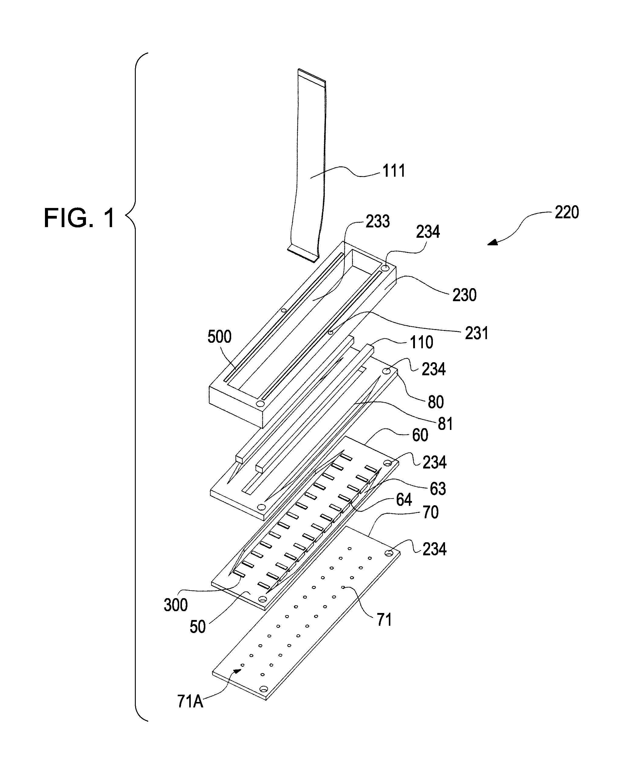
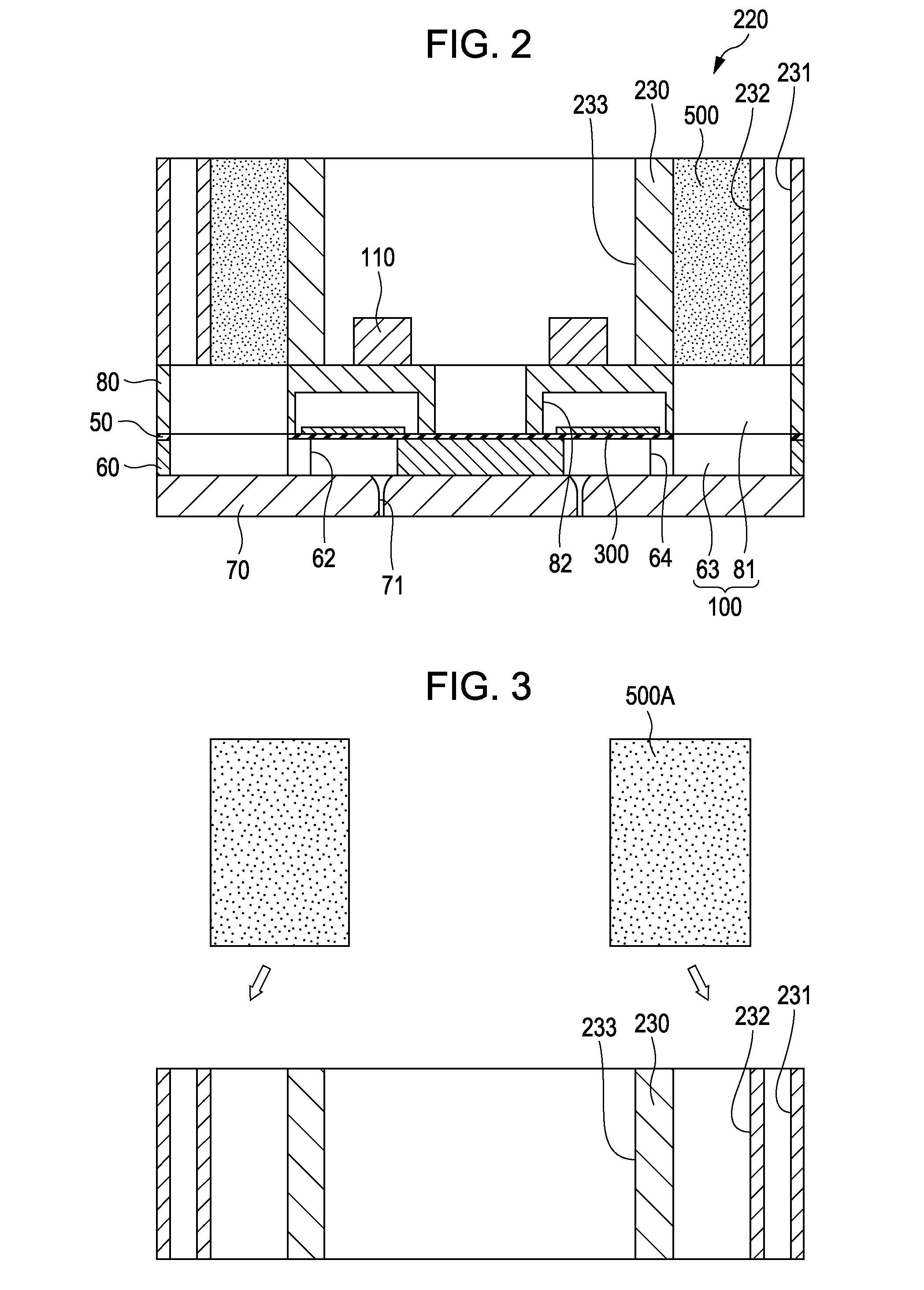
[0032]FIG. 1 is an exploded perspective view illustrating an ink jet recording head as an example of a liquid ejecting head according to the first embodiment of the invention. FIG. 2 is a cross-sectional view illustrating the ink jet recording head.
[0033]As shown in FIGS. 1 and 2, a flow path formation substrate 60 constituting an ink jet recording head 220 is made of a silicon single crystal substrate in the embodiment. An elastic film 50 made of silicon dioxide is formed on one surface side of the flow path formation substrate 60. Two rows of pressure generation chambers 62 are formed on the flow path formation substrate 60 by performing anisotropic etching from the other surface side of the flow path formation substrate 60. A plurality of pressure generation chambers 62 divided by a plurality of separation walls are arranged in parallel in the width direction. Communicating portions 63 are formed on outer sides of the rows of the pressure generation chambers 62 in the longitudina...
second embodiment
[0055]FIG. 6 is a cross-sectional view illustrating a recording head according to a second embodiment. Members of which operations are the same as those in the first embodiment are denoted with the same reference numerals and so description is not repeated.
[0056]As shown in FIG. 6, a concave portion 235 is provided on a part of a wall surface constituting each reservoir 100 of the head case 230, and a foam member 501 is provided in each concave portion 235. That is, the foam member 501 is provided in each concave portion 235 provided on the wall surface of each reservoir 100. Therefore, if pressure fluctuation is caused in the reservoir 100, the foam member 501 is concaved (deformed) in the thickness direction so as to absorb energy of the pressure waves. The foam member 501 does not substantially absorb ink because the foam member 501 is formed with closed cells. Further, a displacement amount of the foam member 501 due to pressure fluctuation is significantly large. Therefore, the...
third embodiment
[0058]FIG. 7 is a cross-sectional view illustrating a recording head according to a third embodiment. Members of which operations are the same as those in the first embodiment are denoted with the same reference numerals and so description is not repeated.
[0059]As shown in FIG. 7, foam members 502 are provided on wall surfaces of the reservoir formation substrate 80. If pressure fluctuation is caused in each reservoir 100, each foam member 502 is concaved (deformed) in the thickness direction so as to absorb energy of the pressure waves by providing the foam member 502 on the liquid flow path (reservoir 100 in the embodiment). The foam member 502 does not substantially absorb ink because the foam member 502 is formed with closed cells. Further, a displacement amount of the foam member 502 due to pressure fluctuation is significantly large. Therefore, the foam member 502 can effectively absorb energy of the pressure waves at a small area. In the embodiment, pressure waves in accompan...
PUM
 Abstract
Description
Claims
Application Information