Liquid droplet discharge head and method of manufacturing the liquid droplet discharge head

Inactive Publication Date: 2006-09-28
FUJIFILM BUSINESS INNOVATION CORP
View PDF1 Cites 3 Cited by
  • Summary
  • Abstract
  • Description
  • Claims
  • Application Information

AI Technical Summary

Benefits of technology

[0010] In view of these circumstances, it is an object of the present invention to obtain a liquid droplet discharge head and a method of ma

Problems solved by technology

For this reason, the number of man-hours significantly

Method used


Image

  • Liquid droplet discharge head and method of manufacturing the liquid droplet discharge head
  • Liquid droplet discharge head and method of manufacturing the liquid droplet discharge head
  • Liquid droplet discharge head and method of manufacturing the liquid droplet discharge head

Examples


Embodiment Construction

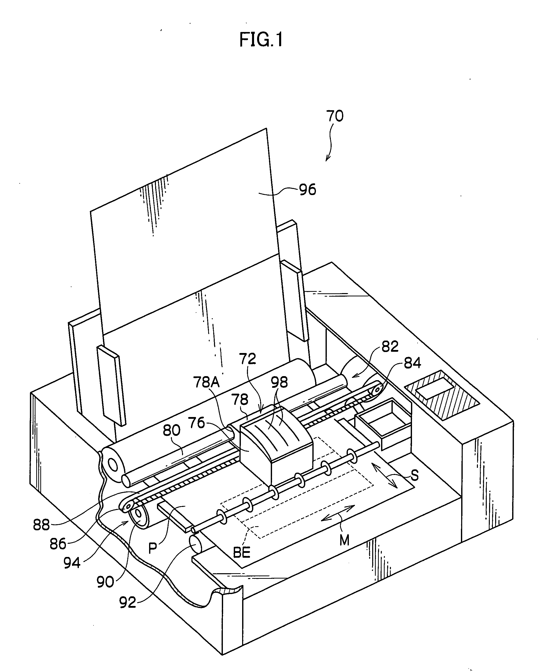
[0066] An inkjet recording head pertaining to an embodiment of the invention will be described below. First, an inkjet recording apparatus 70 shown in FIG. 1 will be described.

[0067] The inkjet recording apparatus 70 uses recording paper P as a recording medium. The direction in which the recording paper P is conveyed in the inkjet recording apparatus 70 is a sub-scanning direction and will be represented by arrow S, and the direction orthogonal to the conveyance direction is a main scanning direction and will be represented by arrow M.

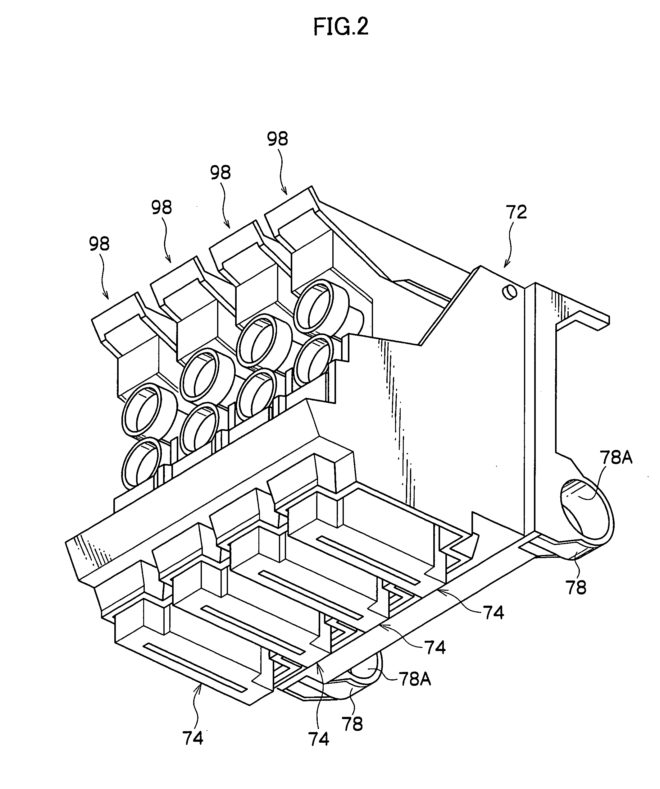
[0068] The inkjet recording apparatus 70 includes a carriage 76 in which is loaded an inkjet recording unit 72 of the respective colors of black, yellow, magenta and cyan. A pair of brackets 78 is disposed in the carriage 76 such that the brackets 78 protrude upstream in the conveyance direction of the recording paper P, and a circular opening 78A is disposed in the brackets 78. A shaft 80 that is disposed along the main scanning direction is insert...


PUM


Abstract

A method of manufacturing a liquid droplet discharge head including nozzles that discharge liquid droplets, pressure chambers that are communicated with the nozzles and filled with liquid droplets, a diaphragm that configures part of the pressure chambers, and piezoelectric member groups that are configured by joining, to the surface of the diaphragm, piezoelectric plates that form groove portions and are processed in a matrix, with the piezoelectric member groups including piezoelectric elements that cause the diaphragm to be displaced as a result of a voltage being applied to the piezoelectric elements, the method comprising: processing the piezoelectric plates in a matrix to prepare the piezoelectric member groups; and joining the piezoelectric member groups to the diaphragm in a state where mutual boundaries of the piezoelectric member groups have been fitted together and with a predetermined clearance being disposed.

Description

CROSS-REFERENCE TO RELATED APPLICATION [0001] This application claims priority under 35 USC 119 from Japanese Patent Applications No. 2005-087155 and No. 2005-237484, the disclosures of which are incorporated by reference herein. BACKGROUND OF THE INVENTION [0002] 1. Field of the Invention [0003] The present invention relates to a method of manufacturing a liquid droplet discharge head that discharges liquid droplets and to a liquid droplet discharge head manufactured by this method. [0004] 2. Description of the Related Art [0005] Conventionally, there have been known inkjet recording apparatus that selectively discharge ink droplets from plural nozzles of an inkjet recording head (sometimes referred to simply as a “recording head” below) that reciprocally moves in a main scanning direction, and which print characters and images on recording media such as recording paper conveyed in a sub-scanning direction. [0006] The recording head is configured by nozzles that discharge ink dropl...

Claims


Application Information

Patent Timeline
IPC IPC(8): B41J2/045
CPCB41J2/14233B41J2/161B41J2/1626B41J2/1632B41J2002/14459B41J2202/11B41J2202/20
Inventor MATSUZAKI, HIROKAZUSETO, SHINJIKANDA, TORAHIKONOTSU, KATSUHIROUMEHARA, SHIGERU
Owner FUJIFILM BUSINESS INNOVATION CORP
Why Eureka
Try Eureka