Kitchen device with suction foot

a technology of suction feet and kitchen devices, which is applied in the direction of kitchen equipment, household applications, fastening means, etc., can solve the problems of affecting the safety of users, and hardly detachable surfaces of appliances

Inactive Publication Date: 2018-06-05
KONINKLJIJKE PHILIPS NV
View PDF38 Cites 0 Cited by
  • Summary
  • Abstract
  • Description
  • Claims
  • Application Information

AI Technical Summary

Benefits of technology

[0009]The actuating force created by a user when holding the device is advantageously transferred into a releasing force at the suction foot via the actuator. With this arrangement, the user can easily pull the device from the surface. In other words, the invention allows the device with the suction foot to be released from the surface with improved ease of use, because holding the device and releasing the device from the surface effectively have become a single, intuitive manual action by the user.
[0033]This allows easy release of the suction feet by exerting two separate releasing forces on the suction feet. Attaching the actuator to the grip area provides a more stable integration of the actuator into the grip, because it prevents loose movement of the actuator in the grip. Moreover, such a configuration is more durable, avoiding continuous stress at a central part of the actuator.

Problems solved by technology

However, such known solution to stabilize kitchen appliances on a flat surface has the major drawback that afterwards, when a user wants to move the appliance, for example after the user has finished using the appliance and wants to move it to a storage area, the appliance is hardly detachable from the surface, for the mere reason that the suction feet are still preventing the appliance from being moved.
However, this solution is not convenient, may damage the suction feet or the appliance, and can present some dangers to users.

Method used


Image

  • Kitchen device with suction foot
  • Kitchen device with suction foot
  • Kitchen device with suction foot

Examples


Embodiment Construction

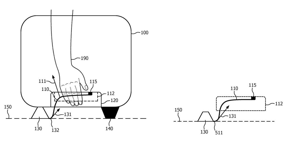
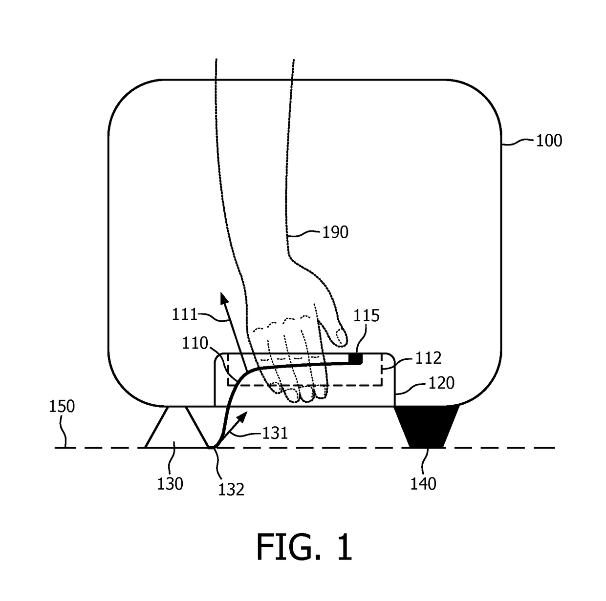
[0050]FIG. 1 illustrates a kitchen device 100 according to the invention. The kitchen device comprises a grip 120 for manually holding the device. The grip defines a grip area 112. The device 100 also comprises a first suction foot 130 attached to the device 100 and arranged to secure the device 100 to a surface 150 by means of suction against the surface 150. The device 100 also comprises an actuator 110 connected to the first suction foot 130 and extending in the grip area 112. The actuator 110 is arranged to transfer an actuating force 111 acting on the actuator 110 into a releasing force 131 acting on the first suction foot 130 to release the first suction foot 130 from the surface 150.

[0051]The device 100 is intended to rest on a surface 150 via a suction foot 130 and a supporting foot 140 that are both attached to the device 100. The device 100 is secured to the surface 150 by means of suction of the suction foot 130 against the surface 150, so that the device 100 cannot easil...


PUM


Abstract

The invention relates to a kitchen device (100) comprising: —a grip (120) for manually holding the device, the grip defining a grip area (112), —a first suction foot (130) attached to the device (100) and arranged to secure the device (100) to a surface (150) by means of suction against the surface (150), —an actuator (110) connected to the first suction foot (130) and extending in the grip area (112), the actuator (110) being arranged to transfer an actuating force (111) acting on the actuator (110) into a releasing force (131) acting on the first suction foot (130) to release the first suction foot (130) from the surface (150). This device can be released from the surface with an improved ease of use, because holding the device and releasing the device from the surface effectively have become a single, intuitive manual action by the user.

Description

[0001]This application is the U.S. National Phase application under 35 U.S.C. § 371 of International Application No. PCT / EP2014 / 077591, filed on Dec. 12, 2014, which claims the benefit of International Application No. 14152759.8 filed on Jan. 28, 2014 and International Application No. PCT / CN2013 / 090341 filed on Dec. 24, 2013. These applications are hereby incorporated by reference herein.FIELD OF THE INVENTION[0002]The invention relates to kitchen devices, in particular kitchen devices having a suction foot attached to the device for securing the device to a surface.BACKGROUND OF THE INVENTION[0003]To stabilize kitchen appliances on a flat surface, a known solution is to use a plurality of suction feet (also called suction cups) positioned below the appliances, so that when the appliance is put on a flat surface, such as a kitchen table, the suction effect of the suction feet prevents (or at least limits) any movement of the appliance on this surface. Such type of solution is for ex...

Claims


Application Information

Patent Timeline
Patent Type & Authority Patents(United States)
IPC IPC(8): A47J45/02F16B47/00
CPCF16B47/00A47J45/02
Inventor CHEUNG, SAU KANIVARSSON, BENGT IVAR ANDERS
Owner KONINKLJIJKE PHILIPS NV
Why Eureka
Try Eureka