Clasp mechanism

a technology of clasps and mechanisms, applied in mechanical devices, ear rings, transportation and packaging, etc., can solve the problems of difficult operation of this type of clasps and the same drawbacks of clasps

Inactive Publication Date: 2001-09-18
BEARD GUY +2
View PDF14 Cites 8 Cited by
  • Summary
  • Abstract
  • Description
  • Claims
  • Application Information

AI Technical Summary

Benefits of technology

To operate the device, the user grasps the clasp so that the thumb and forefinger rest against the main body and the actuating shoulder part of the keeper arm. Squeezing the main body and the actuating shoulder causes compression of the spring and the actuating shoulder moves into the shoulder cavity of the main body. Because of the centralized pivot, this action causes the mating end of the keeper arm to move inwardly away from the hood end, creating an opening and allowing the hook end to be inserted onto a loop end of a chain, bracelet or necklace. Release of the pressure against the actuating shoulder allows the coiled spring to return the mating end of the keeper arm back into conjunction with the hook arm, closing off the opening and enclosing the loop end securely within the interior portion of the hook end. The pressure of the coiled spring maintains the clasp in this closed position until the device is opened by the user for removal of the loop end.

Problems solved by technology

Because the clasp is of such small size, it is very difficult to operate this type of clasp.
These clasps suffer from the same drawbacks.

Method used


Image

  • Clasp mechanism
  • Clasp mechanism

Examples


Embodiment Construction

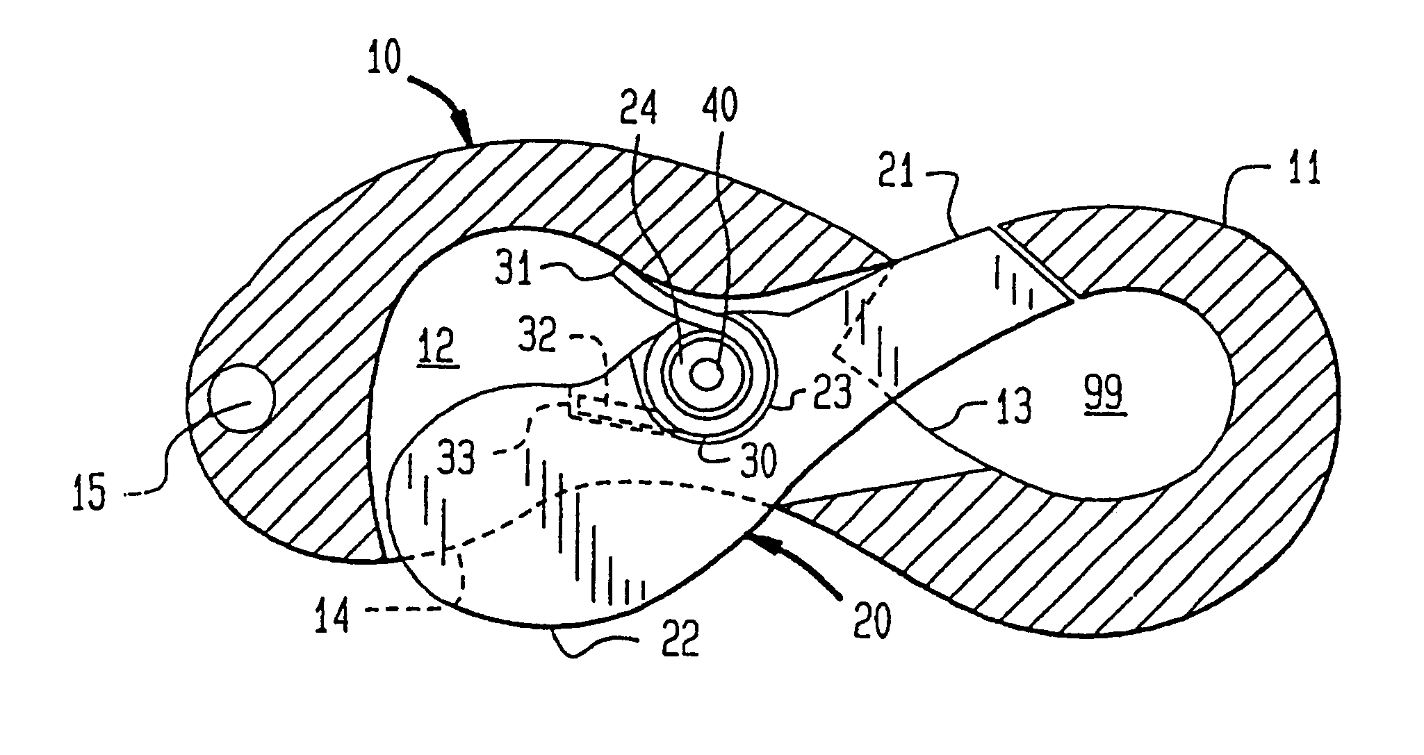
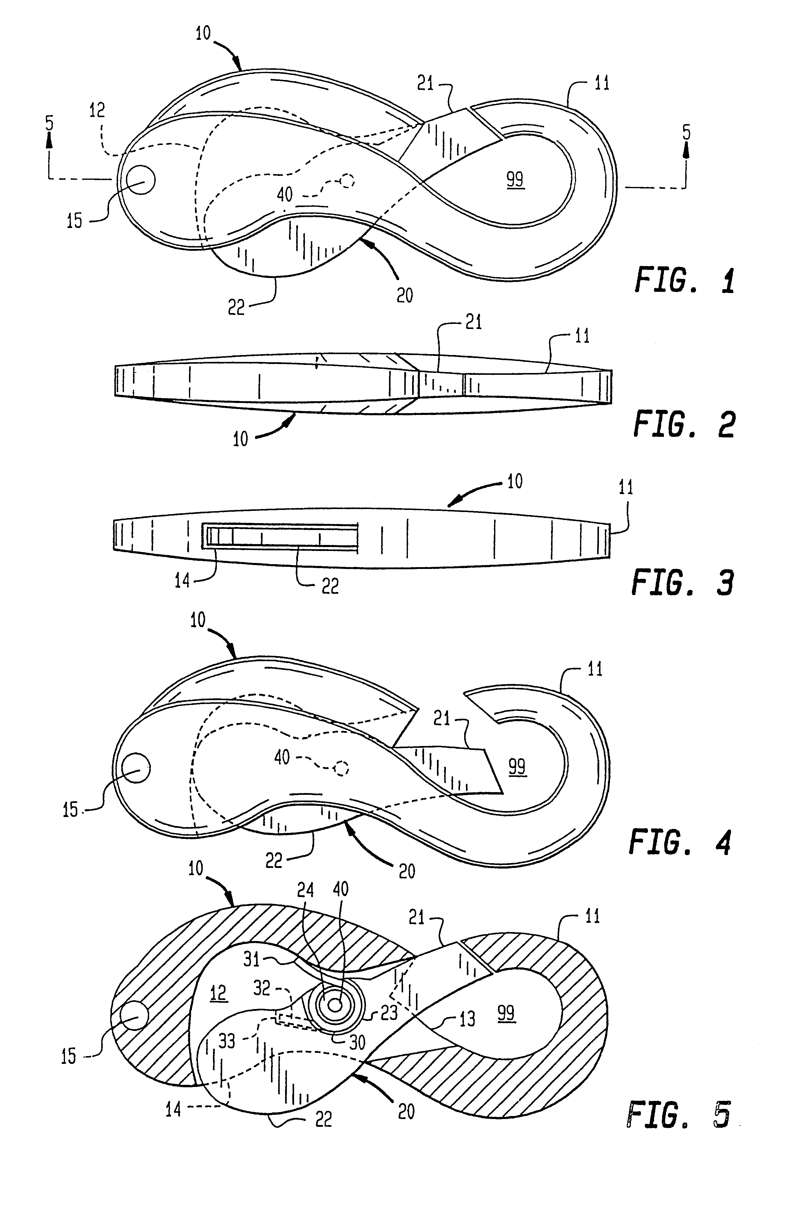
With reference now to the figures, the invention will be described in view of the best mode and preferred embodiment. In general, the invention comprises a main body 10, a keeper arm 20, and a coiled spring 30.

Referring to FIG. 1, the relationship of the main body 10 and the keeper arm 20 is shown. The main body 10 comprises a hook end 11 and linkage attachment means 15 positioned at opposite ends of the main body 10. Linkage attachment means 15 is used for connecting the clasp to one end of the chain or article which requires joining, and can be an aperture (as shown) for receiving a chain link, a loop extending from the main body 10, or any other typical structure known in the art for accomplishing this attachment. This attachment will usually be a permanent attachment. Extending through the main body 10 is the keeper arm 20. Keeper arm 20 comprises a mating end 21 and an actuating shoulder 22. Mating end 21 acts in conjunction with hook end 11 of the main body 10 to form a closed...


PUM


Abstract

A clasp mechanism having a main body, a keeper arm and a spring, where the keeper arm extends through the main body in an arm cavity. The keeper arm is pivotally attached to said main body to operate in a scissor-like manner. The keeper arm has a mating end which abuts a hook end on the main body to form a closed interior space and an actuating shoulder extending from the main body. The spring maintains the mating end in the closed position abutting the hook end until the actuating shoulder is pressed into the main body by the user.

Description

BACKGROUND OF THE INVENTIONThis invention relates generally to the field of clasp mechanisms used to join or close upon themselves chains, ropes or other articles. More particularly, the invention is directed to the field of such clasps used with jewelry chains, bracelets, necklaces, etc.Clasps used in the jewelry field to join the ends of bracelets and necklaces are of necessity very small so that the clasp mechanism will not detract from the ornamentation of the piece. Such clasps must also be very secure since the jewelry can be very valuable. It is therefore desirable to have clasps which are designed and constructed to be effective against accidental opening, as well as to be easily workable by the user. It is also preferable that the clasp have some artistic merit to it as well. The mechanisms should also be of relatively simple construction.Typical jewelry clasps operate with spring rings which require the user to slidingly move a curved pin contained within a tubular body to...

Claims


Application Information

Patent Timeline
Patent Type & Authority Patents(United States)
IPC IPC(8): A44C5/18A44C5/20F16B45/00F16B45/02
CPCA44C5/2038F16B45/02Y10T24/45293Y10T24/45319Y10T24/45356
Inventor SHRADER, JAMES P.BEARD, GUY
Owner BEARD GUY
Why Eureka
Try Eureka