Localized automatic fire extinguishing apparatus

a fire extinguishing apparatus and automatic technology, applied in the direction of fire alarms, optical radiation measurement, instruments, etc., can solve the problems of fires that are much more difficult to extinguish, slow and inefficient heat sensors, injuries and property damage, etc., and achieve the effect of quick identification and extinguishing a fir

Inactive Publication Date: 2006-05-02
THOMAS ALAN E +1
View PDF10 Cites 14 Cited by
  • Summary
  • Abstract
  • Description
  • Claims
  • Application Information

AI Technical Summary

Benefits of technology

[0006]In view of the above-mentioned disadvantages of the prior art, it is an objective of the present invent

Problems solved by technology

Because these types of heat sensors are slow and inefficient, by the time the fire is detected it has usually spread over a large area causing injuries and property damage before it is extinguished.
Additional

Method used


Image

  • Localized automatic fire extinguishing apparatus
  • Localized automatic fire extinguishing apparatus
  • Localized automatic fire extinguishing apparatus

Examples


Embodiment Construction

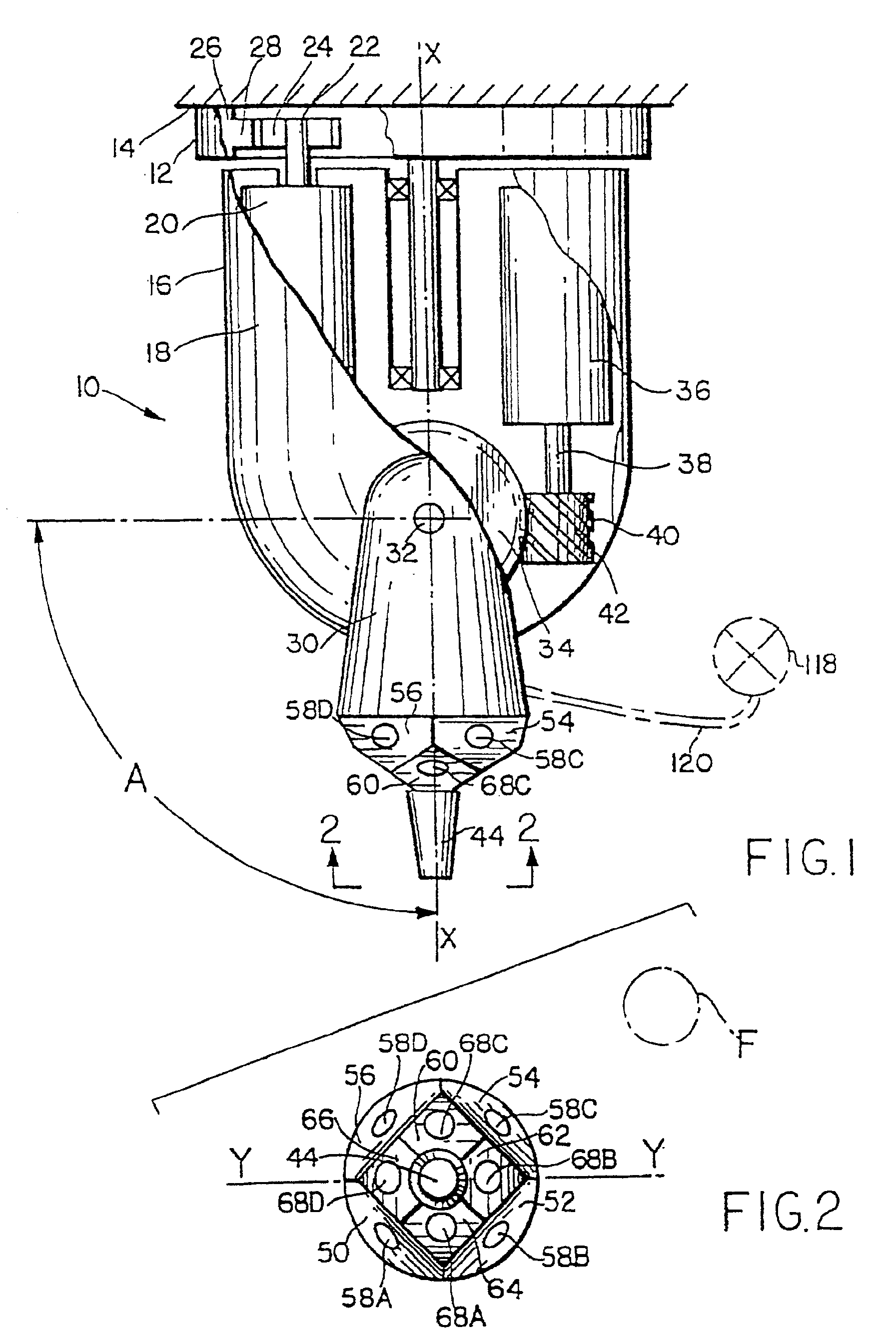
[0015]Referring now to the drawings, and more particularly FIGS. 1 and 2, an apparatus 10 constructed in accordance with this invention includes a base 12 mounted on a ceiling 14 and a turret 16. The turret 16 includes a generally cylindrical housing 18 open at the top. A motor 20 secured inside housing 18 is used to rotate the turret 16 about a vertical axis X—X. For this purpose, motor 20 has a shaft 22 terminating in a toothed gear 24. Base 12 is provided with a stationary ring 26 having radially inwardly extending teeth 28. Teeth 28 engage gear 24 so that as the shaft 22 is turned by motor 20, the turret 18 rotates with respect to the base.

[0016]An arm 30 is mounted on housing 18 by a horizontal shaft 32. Shaft 32 also supports a toothed gear 34 disposed inside housing 18. Also within housing 18 there is provided a second motor 36 with a shaft 38 and a gear 40. Importantly, gear 40 has teeth 42 disposed at an angle and engaging the toothed wheel 34 such that as the gear 40 is tu...


PUM


Abstract

An automated fire extinguishing apparatus includes a turret with a nozzle connected to a water supply. A plurality of sensors are used to detect a fire monitored by the apparatus. The signals from the sensors are used to aim the nozzle toward the fire and to initiate water ejection therefrom. After the fire is extinguished the water is turned off.

Description

CROSS-REFERENCE TO RELATED APPLICATION [0001]This reissue application is a continuation of U.S. patent application Ser. No. 09 / 137,960, filed Aug. 20, 1998, now U.S. Pat. No. RE 37,493, which was a reissue of U.S. Pat. No. 5,548,276, which resulted from U.S. patent application Ser. No. 08 / 158,989.<?insert-end id="INS-S-00001" ?>BACKGROUND OF THE INVENTION[0002]1. Field of Invention[0003]This invention pertains to an automatic fire extinguishing apparatus, and more particularly to an apparatus which locates a fire in a room and directs a stream of water or other agent from a nozzle at the fire for extinguishing it.[0004]2. Description of the Prior Art[0005]Automatic sprinkler installation are common in both residential and commercial establishments and are frequently mandated by local fire codes. However these sprinkler installations consist merely of a plurality of water nozzles set off by mechanical heat sensors. Because these types of heat sensors are slow and inefficient, b...

Claims


Application Information

Patent Timeline
IPC IPC(8): G08B17/12A62C37/38
CPCA62C37/38
Inventor THOMAS, ALAN E.
Owner THOMAS ALAN E
Why Eureka
Try Eureka