Multiple plane weigh platter for multiple plane scanning systems

a technology of multiple plane scanning and weigh platter, which is applied in the direction of weighing apparatus details, instruments, sensing record carriers, etc., can solve the problems of increasing the area of the weigh platter, affecting the mechanical stability and affecting the operation of the weighing system

Inactive Publication Date: 2008-02-19
DATALOGIC SCANNING
View PDF25 Cites 52 Cited by
  • Summary
  • Abstract
  • Description
  • Claims
  • Application Information

AI Technical Summary

Problems solved by technology

Multiple plane scanners such as the MAGELLAN™ unit, however, may encounter several problems when a weigh scale is being incorporated.
Since these systems are often used in locations where space is a significant limitation, such as a supermarket checkout stand, the addition of a second scan plane often comes at the expense of decreased area of the horizontal weigh platter.
This decreases in area increases the likelihood that the vertical scan components, vertical scan window, and their associated housing will interfere mechanically with an object placed on the weigh platter to be weighed.
Moreover, the limited size of the weigh platter may result in an object being weighed (depending upon its size) to extend past the edge of the platter onto the counter potentially resulting in an inaccurate weight measure.
In a dual plane scanner, since there can be no air gap or weigh platter extension on the side of the weigh platter adjacent the vertical scan window, debris may accumulate under the weigh platter which in turn may obstruct the horizontal scan window or may inhibit proper scale operation.

Method used


Image

  • Multiple plane weigh platter for multiple plane scanning systems
  • Multiple plane weigh platter for multiple plane scanning systems
  • Multiple plane weigh platter for multiple plane scanning systems

Examples


Embodiment Construction

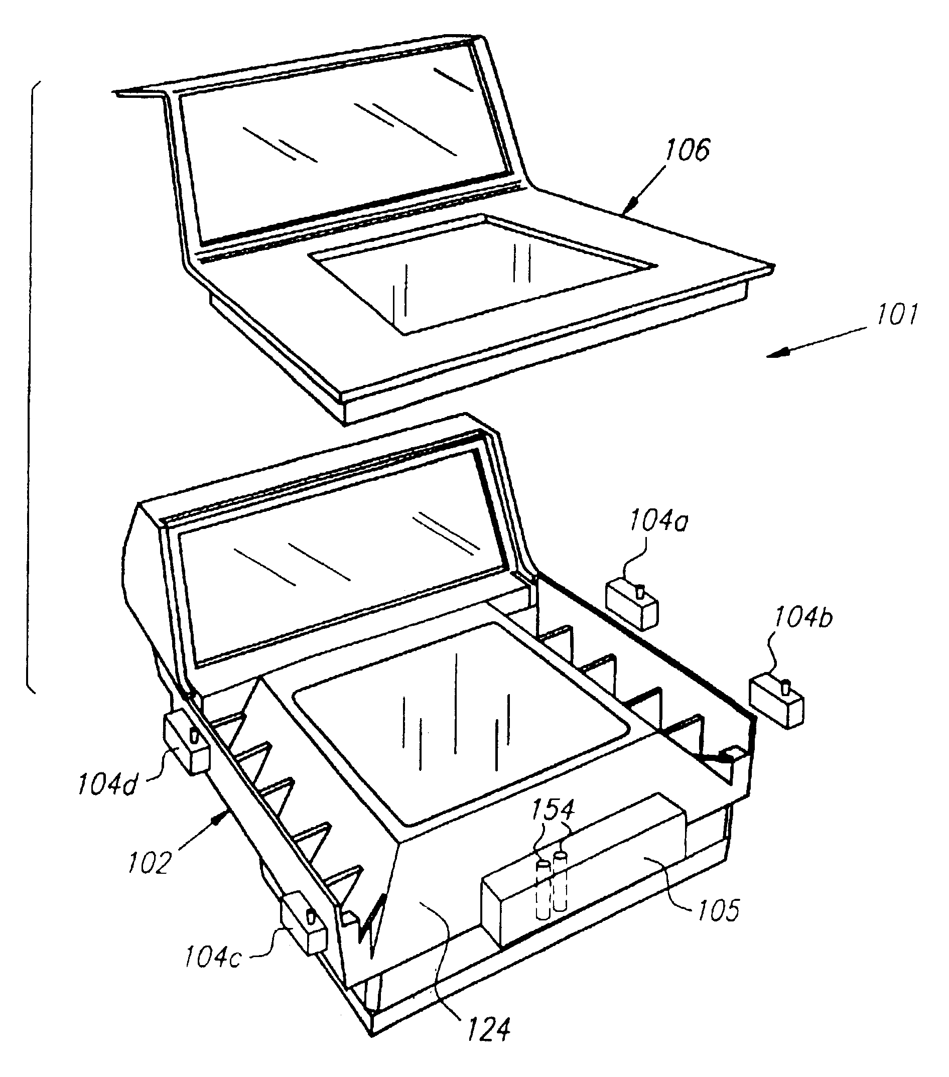
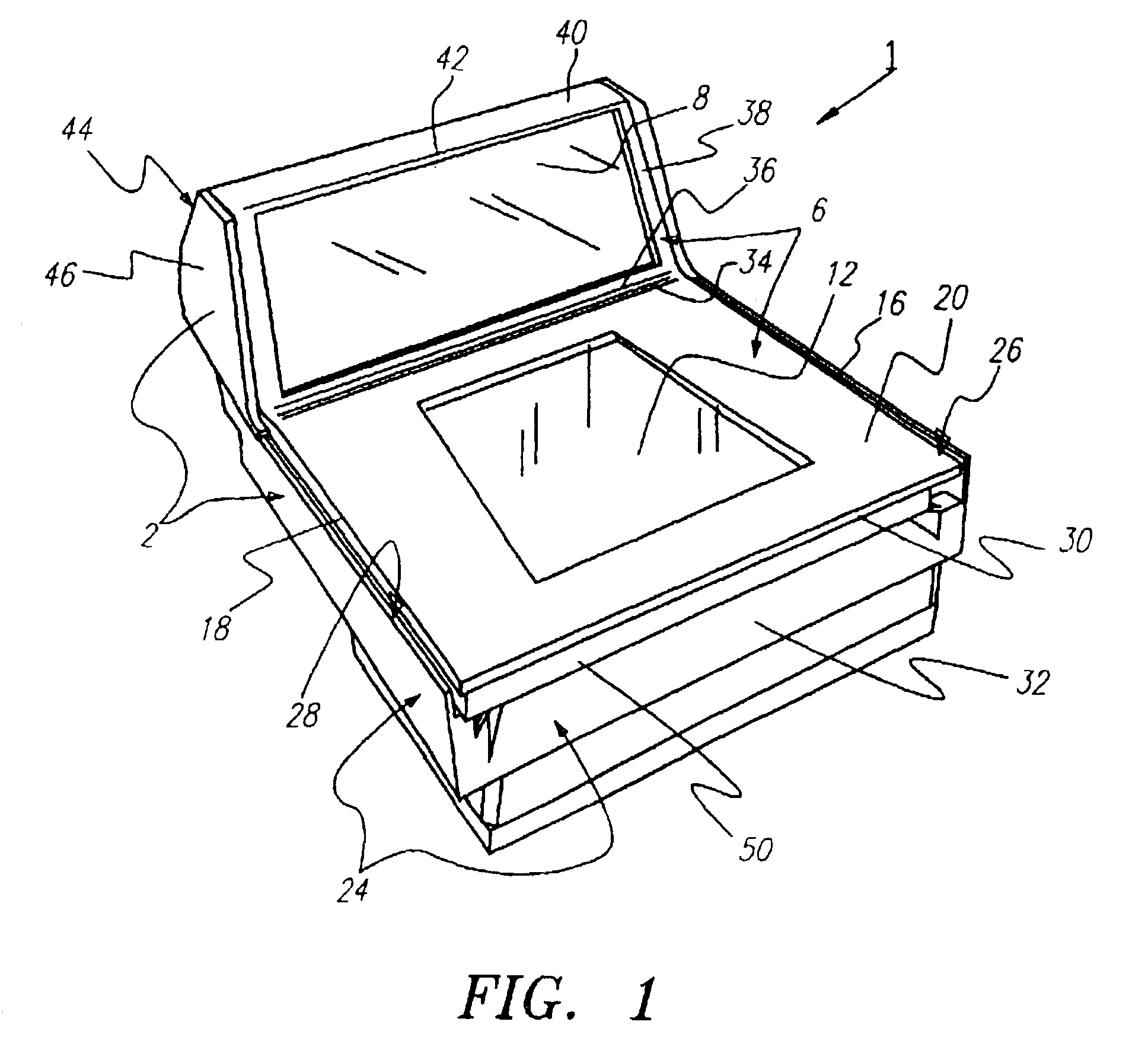
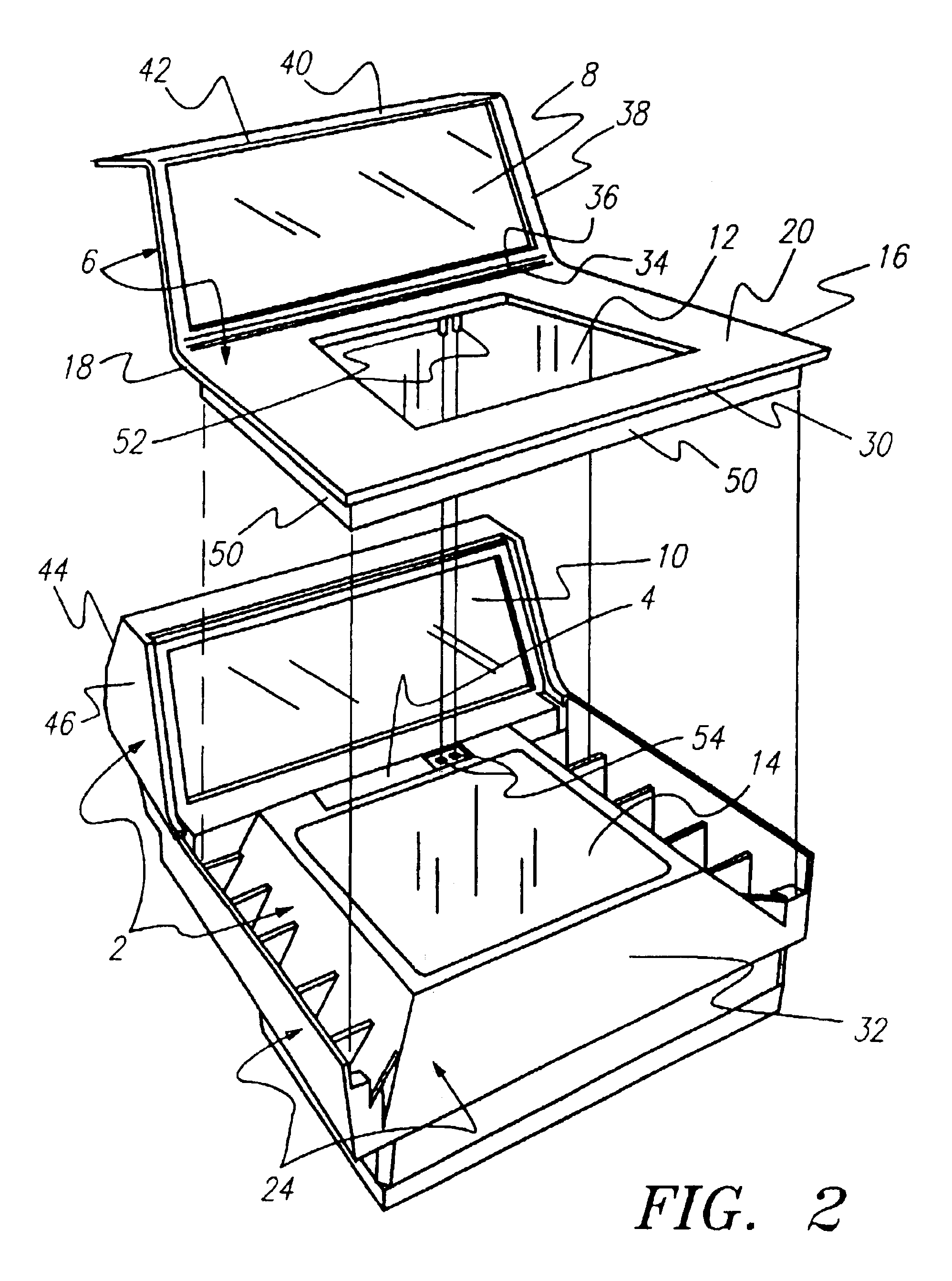
[0022]The preferred embodiments will now be described with reference to the drawings. FIGS. 1-5 illustrate a two-plane scanner / weighing apparatus 1 including a scanner 2 with an integral load cell 4 and a two-plane spiderless weigh platter 6. When assembled the vertical platter window 8 is positioned in front of the vertical scan window 10 and the horizontal platter window 12 is positioned over the horizontal scan window 14. This relative positioning of the platter windows 8, 12 to the scan windows 10, 14 allows optical beams generated by the scan engine(s) to pass out through the scan windows and platter windows, and allows the resulting optical signals from a scanned barcode to pass in through the platter windows and the scan windows for detection and decoding. The window 8 may be oriented perfectly vertical, or it may be angled somewhat from absolute vertical as best shown in FIG. 3.

[0023]The lateral side edges 16, 18 of the horizontal section 20 of the weigh platter 6 and the ho...


PUM


Abstract

A multi-plane scanner having a dual plane scanner with a horizontal window and a vertical window and a load cell / weigh platter weighing apparatus such that the weigh platter itself is a dual plane object with vertical and horizontal sections. The size and orientation of the planes of the weigh platter correspond to the size and orientation of the scan windows of the dual plane scanner, and each plane of the weigh platter has a transparent area (typically central), or “platter window”, corresponding to a respective scan windows of the scanner for allowing transmission of scanned optical beams and optical barcode signals through each of the planes of the weigh platter. The platter is sufficiently rigid to permit accurate weighing whether the object being weighed is placed solely on the horizontal section of the platter or in part on the vertical section. The vertical and horizontal sections of the platter are sealed together to prevent passage of debris therebetween.

Description

RELATED APPLICATIONS[0001]This application is a divisioncontinuation of Ser. No. 08 / 539,584 filed Oct. 5, 1995 <?delete-start id="DEL-S-00002" date="20080219" ?>noe<?delete-end id="DEL-S-00002" ?> <?insert-start id="INS-S-00002" date="20080219" ?>now U.S. Pat. No. 5,834,2085,834,708 which is a continuation-in-partclaims the benefit of provisional application Ser. No. 60 / 000,052 filed Jun. 8, 1995 which is hereby incorporated by reference.BACKGROUND OF THE INVENTION[0002]The field of the present invention relates to fixed optical reading systems, for example bar code scanning systems, which include multiple windows through which optical reading may be accomplished.[0003]Fixed barcode scanners having multiple windows capable of reading objects in a variety of orientations have been on the market for some time. One such “multi-plane” scanner is described in U.S. Pat. No. 5,475,207 entitled “Multiple Plane Scanning System for Data Reading Applications”, which is her...

Claims


Application Information

Patent Timeline
Patent Type & Authority Patents(United States)
IPC IPC(8): G06K7/10G01G19/414G01G21/22G01G21/28
CPCG01G19/4144G01G21/22G01G21/28
Inventor SVETAL, MICHAEL P.BOBBA, MOHAN LEELARAMASCHLER, MATT D.OLDHAM, GARY J.
Owner DATALOGIC SCANNING
Why Eureka
Try Eureka