Method of using removable cleat system

a cleat system and cleat technology, applied in the direction of fastenings, fastening means, press-button fasteners, etc., can solve the problems of pressure against the socket, the use of screw-type attachment methods is especially laborious, and none of these systems have found wide acceptance among users

Inactive Publication Date: 2008-08-19
CLEATS
View PDF35 Cites 19 Cited by
  • Summary
  • Abstract
  • Description
  • Claims
  • Application Information

AI Technical Summary

Benefits of technology

[0011]A representative embodiment of the present invention includes a method of installing a removable cleat to the sole of a shoe. The method includes providing a cleat having (1) a ground-engaging structure for engaging the ground; and (2) an attachment structure for removably attaching the cleat to the footwear. The attachment structure has a vertical axis, a base to which the top of the ground-engaging member is attached, and a plurality of extensions attached to the base. A receptacle is provided for receiving and holding the cleat, the receptacle being mounted in the sole of a shoe. The receptacle has (1) a wall defining a cavity between a receptacle top and a receptacle bottom, wherein portions of the wall extend radially inward toward a central vertical axis of the receptacle so as to define: (i) a plurality of inclines within the cavity, and (ii) a plurality of protuberances within the cavity, each proturbence extending radially inward toward the vertical axis further than the compressible inclines: (2) a restraining ledge attached to the receptacle bottom and extending into the cavity so as to prevent downward movement of an installed cleat; and (3) an opening in the restraining ledge having at least three equi-distantly spaced radially projecting lobes that extend radially outward from the central vertical axis of the receptacle. The cleat extensions are inserted through the receptacle opening into the receptacle cavity. Then, the extensions are engaged above the restraining ledges so that the cleat is securely attached to the receptacle so as to resist rotational movement of the cleat.

Problems solved by technology

Using this screw-type attachment method is especially laborious when one takes into account that a typical golf shoe, for instance, has eleven cleats; as a result, replacing the cleats on a pair of golf shoes entails unscrewing twenty-two cleats and screwing on twenty-two cleats, where each act of unscrewing or screwing entails several turns, typically two and one-half times, for each cleat.
Although some prior-art references show cleat-attachment systems that require less than a full turn, or they require a snap-on arrangement to lock the cleat in place, it appears none of these systems have found wide acceptance amongst users because of shortcomings in stability, ease-of-use, receptacle size and ease-of manufacture.
The skirt is deformed so as to result in a pressure against the socket, the pressure apparently holding the spike from accidentally traveling back up the ramp towards removal.

Method used


Image

  • Method of using removable cleat system
  • Method of using removable cleat system
  • Method of using removable cleat system

Examples


Embodiment Construction

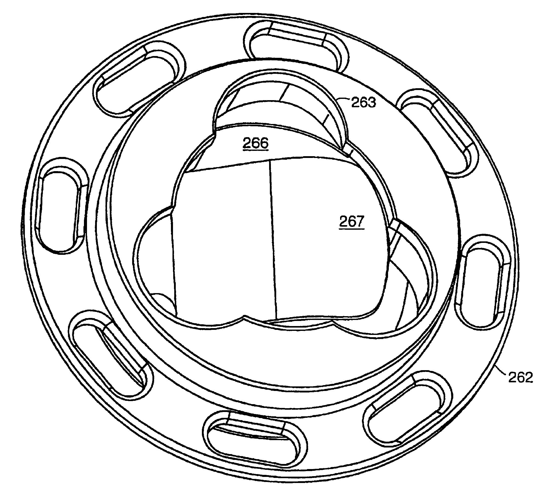
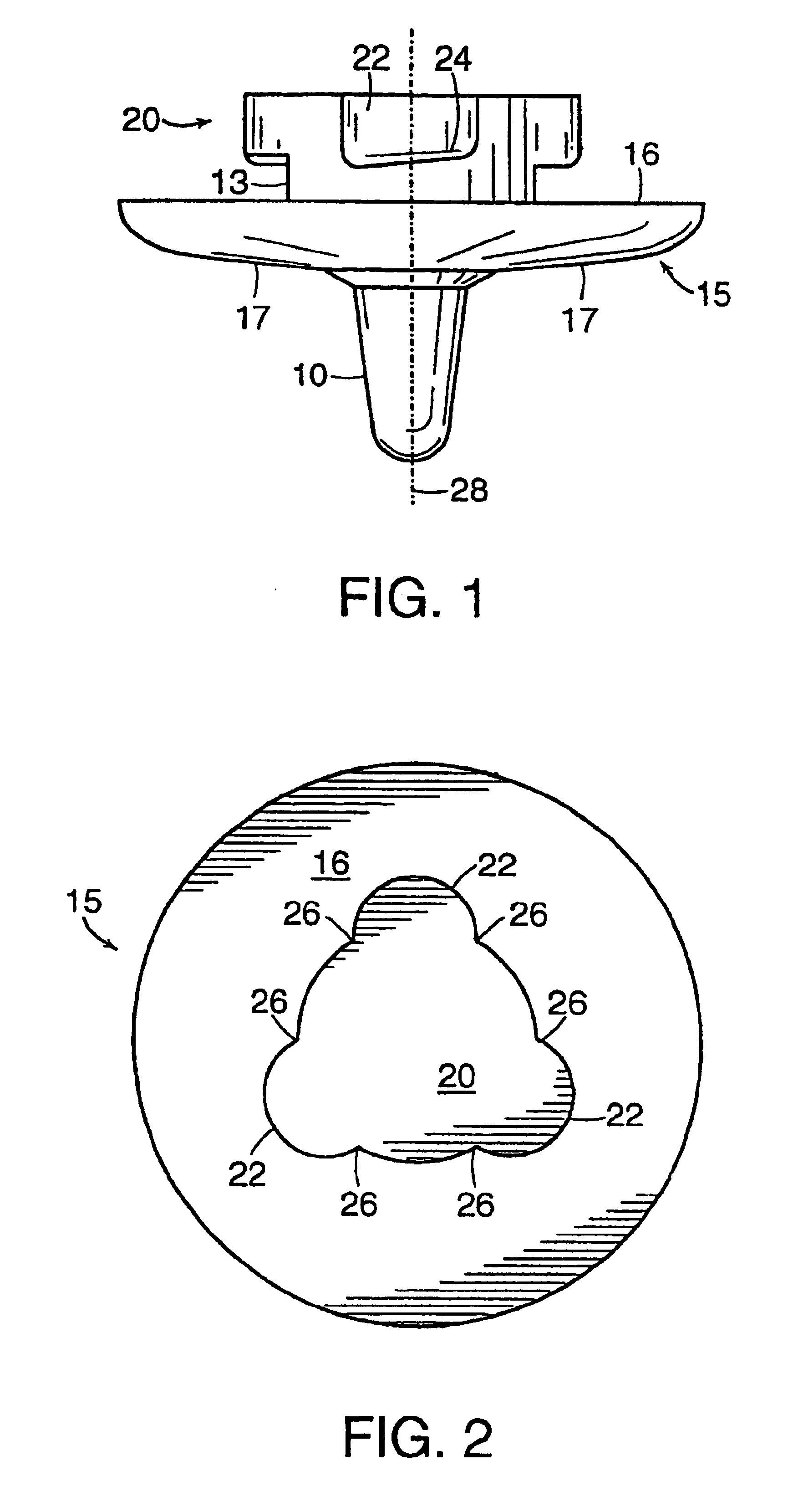
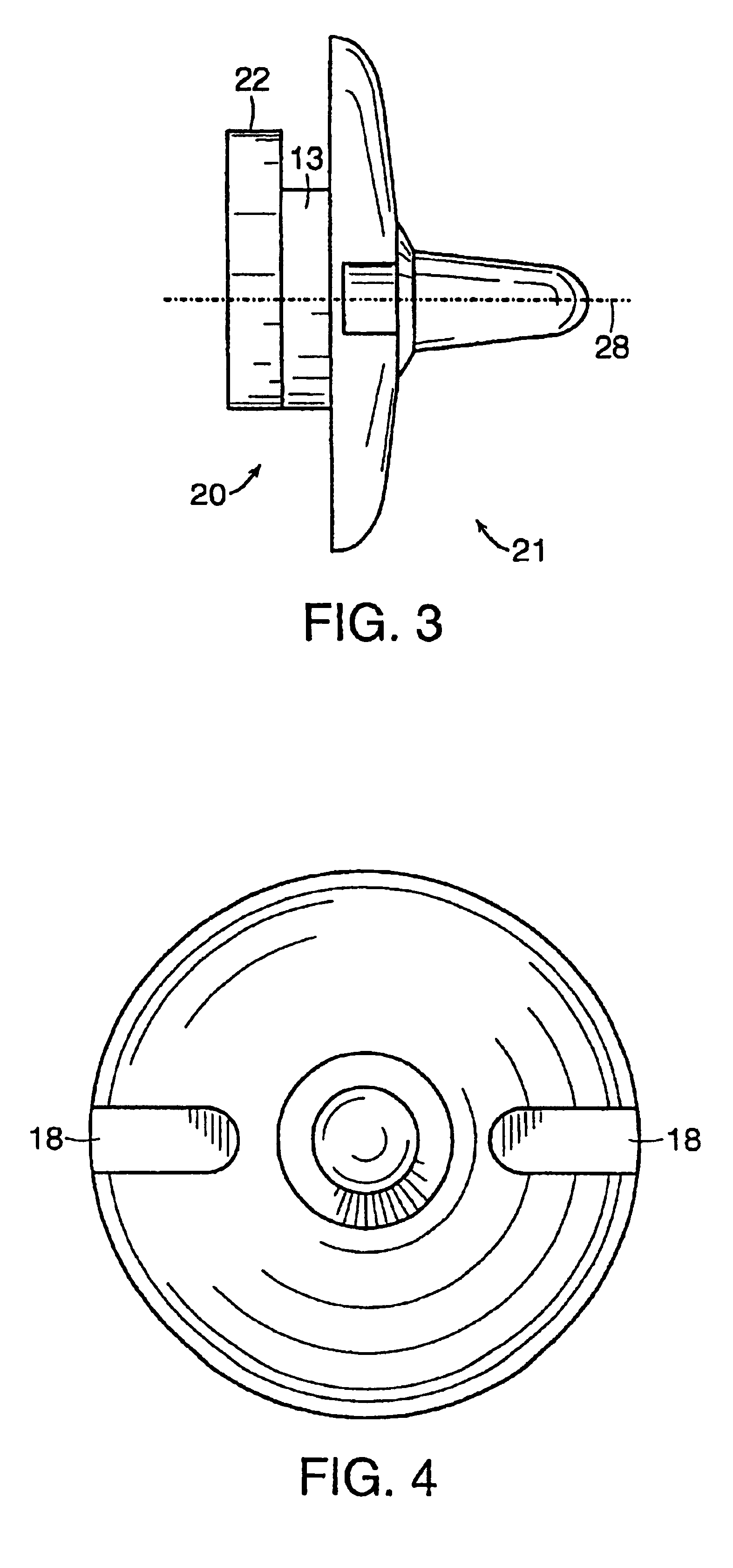
[0052]The invention comprises a system for allowing the quick attachment and release of a wide variety of traction gear. FIG. 1 shows that in one embodiment of the invention, the attachment system would be used to attach cleats, such as those disclosed in U.S. Pat. No. 4,723,366, to the underside of athletic footwear a cleat installed in the bottom of a shoe using the present invention, when viewed from the bottom, has a similar appearance to the preferred embodiment of the invention disclosed herein. Evident in FIG. 1 are the bottom side 17 and top side 16 of the plastic skirt 15, the ground-engaging head portion 10 of the cleat, a base 13 to which the plastic skirt and ground-engaging portion are attached and a retaining member 20, which in this case is a base 13 with three rounded extensions 22, all of which are positioned around a central axis 28. In a preferred embodiment of the invention, the top 16 of the skirt 15 is slightly concave, and the bottom 17 of the skirt 15 is some...


PUM


Abstract

A removable cleat for a shoe is described. The cleat includes a ground-engaging structure for engaging the ground. An attachment structure is for removably attaching the cleat to the footwear. The attachment structure has a vertical axis, a base to which the top of the ground-engaging member is attached, and multiple extensions projecting radially outward from the base. The extensions are adapted for insertion into a cleat receptacle in the shoe to engage a receptacle attachment structure within the receptacle, so that when the cleat is attached to the receptacle, each cleat extension will be securely engaged above a receptacle restraining ledge.

Description

[0001]This is a continuation of application Ser. No. 09 / 641,117, filed on Aug. 17, 2000, which is a division of application Ser. No. 09 / 208,180, filed on Dec. 9, 1998, now U.S. Pat. No. 6,108,944, which is a continuation-in-part of application Ser. No. 09 / 062,037, filed on Apr. 17, 1998, now U.S. Pat. No. 6,151,805, which is a continuation-in-part of application Ser. No. 08 / 774,585, filed on Dec. 23, 1996, now U.S. Pat. No. 5,768,809.[0002]Provisional application No. 60 / 010,099, filed on Jan. 17, 1996.FIELD OF THE INVENTION[0003]This invention relates to the mounting of traction gear on the bottom of footwear, in particular, athletic footwear.BACKGROUND ART[0004]Conventional traction gear presently in use employ an attachment means consisting of screwing the traction gear into the mated receiving receptacle in the bottom of the footwear. Using this screw-type attachment method is especially laborious when one takes into account that a typical golf shoe, for instance, has eleven clea...

Claims


Application Information

Patent Timeline
Patent Type & Authority Patents(United States)
IPC IPC(8): A43B5/00A43B23/28A43C15/00A43C15/02A43C15/16F16B21/04
CPCA43C15/161Y10T24/4522Y10T24/2775F16B21/04
Inventor SAVOIE, ARMAND J.
Owner CLEATS
Why Eureka
Try Eureka