Optical assembly, backlight unit and display apparatus thereof

a backlight unit and optical assembly technology, applied in the direction of illuminated signs, display means, instruments, etc., can solve the problem that the backlight unit cannot produce a slim lcd device, and achieve the effect of improving the image quality of the display pictur

Active Publication Date: 2019-10-22
LG ELECTRONICS INC
View PDF88 Cites 6 Cited by
  • Summary
  • Abstract
  • Description
  • Claims
  • Application Information

AI Technical Summary

Benefits of technology

[0005]An object of the present invention is to provide a backlight unit capable of improving an image quality of a display picture and a backlight unit and a display apparatus thereof.
[0007]According to an aspect of the present invention, a backlight unit can reduce the thickness of a display apparatus and improve an exterior while simplifying a manufacturing process of the display apparatus by closely contacting the backlight unit to a display panel.
[0008]Further, it is possible to provide light having uniform luminance to the display panel by disposing the backlight unit so that a plurality of light sources emit in different directions. Accordingly, it is possible to improve the image quality of the display picture.

Problems solved by technology

However, such a backlight unit has a limitation of producing an LCD device that may not be slim.

Method used


Image

  • Optical assembly, backlight unit and display apparatus thereof
  • Optical assembly, backlight unit and display apparatus thereof
  • Optical assembly, backlight unit and display apparatus thereof

Examples


first embodiment

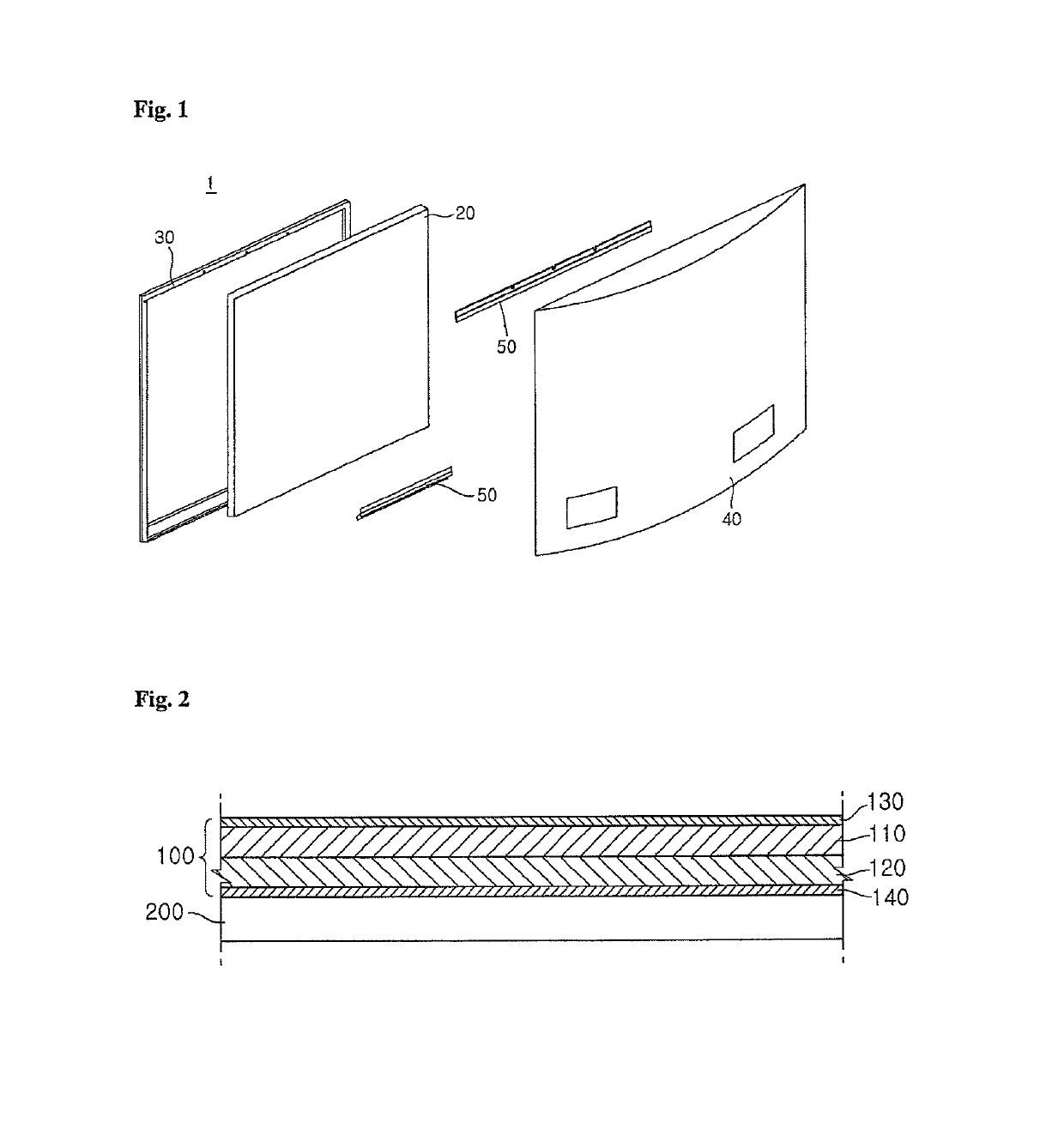
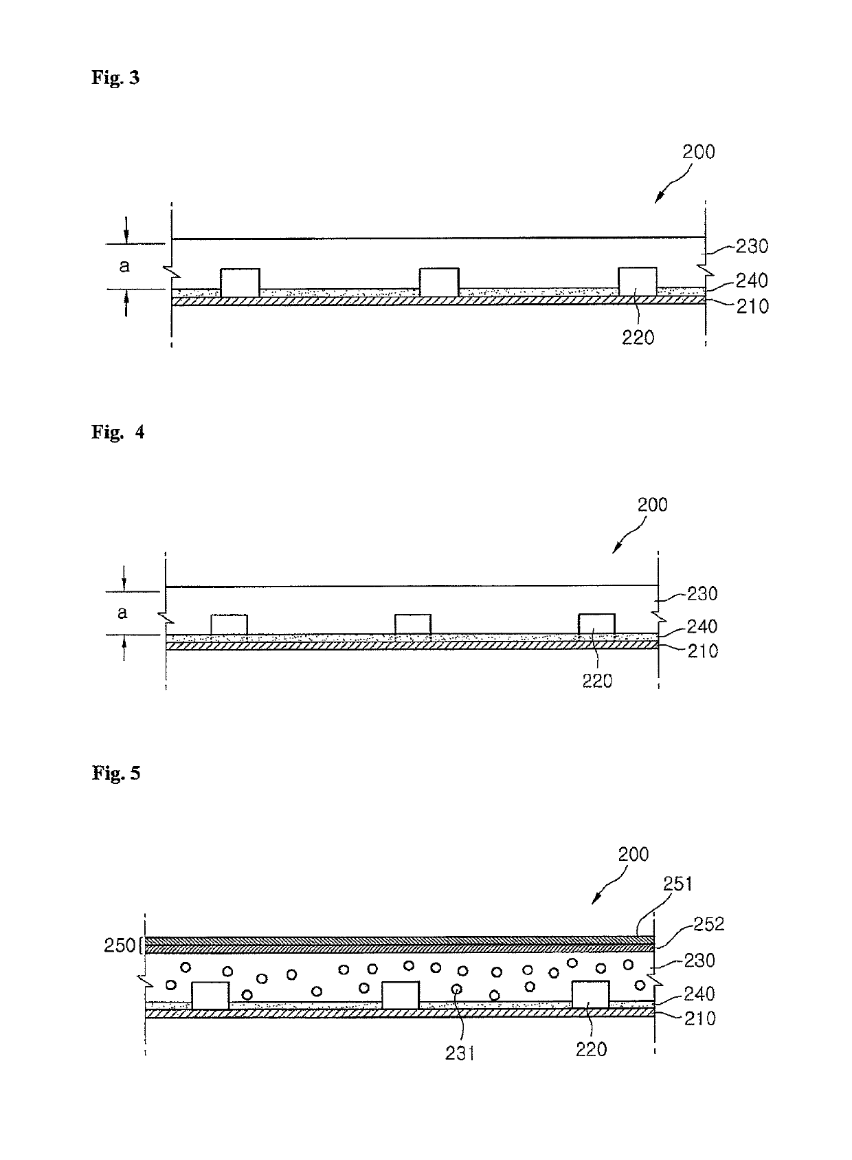
[0059]FIG. 3 is a cross-sectional view illustrating a configuration of a backlight unit according to the present invention. The illustrated backlight unit 200 can include a first layer 210, light sources 220, a second layer 230, and a reflection layer 240. The light sources 220 in the backlight unit 200 are formed below the display panel 100 for providing light throughout the display panel 100 as shown in FIGS. 1 and 2.

[0060]Referring to FIG. 3, the plurality of light sources 220 are formed on the first layer 210 and the second layer 230 is disposed on the top of the first layer 210 to cover the plurality of light sources 220. Preferably the second layer 230 completely encapsulates the light sources 220 formed on the first layer 210, but in another example, thes second layer 230 can cover only certain portions / sides of the light sources 220 formed on the first layer 210.

[0061]The first layer 210 may be a substrate on which the plurality of light sources 220 are mounted. An electrode...

second embodiment

[0080]FIG. 5 is a cross-sectional view illustrating a configuration of a backlight unit according to the present invention. Description of the same components of the backlight unit 200 shown in FIG. 5 as those explained by referring to FIGS. 2 and 3 will now be omitted.

[0081]Referring to FIG. 5, the plurality of light sources 220 can be mounted on the substrate 210 and the resin layer 230 can be disposed on the top of the substrate 210 to cover the light sources 230 entirely or partially. Meanwhile, the reflection layer 240 can be formed between the substrate 210 and the resin layer 230, e.g., on the top of the substrate 210.

[0082]Further, as shown in FIG. 5, the resin layer 230 can include a plurality of scattering particles 231 and the scattering particles 231 can more widely diffuse the light emitted from the light sources 220 by scattering or refracting the incident light.

[0083]The scattering particles 231 can be made of a material having a refractive index different from the ma...

third embodiment

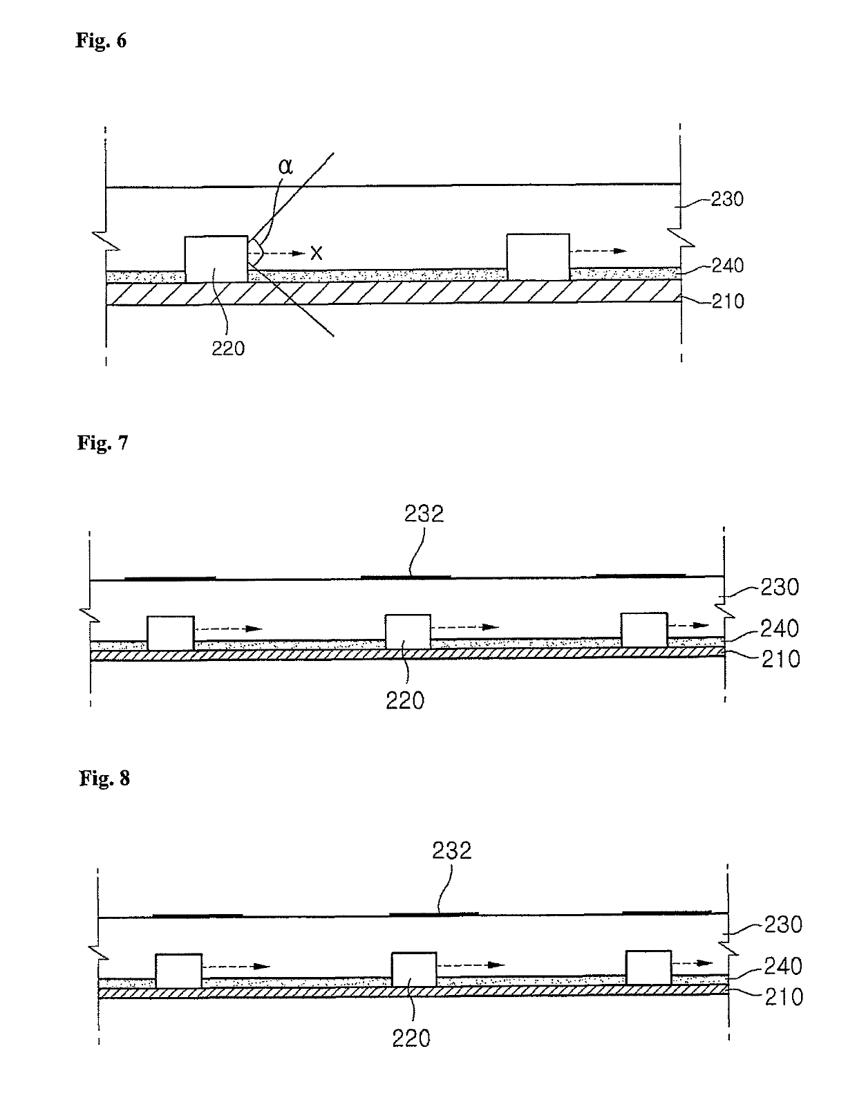
[0096]FIG. 6 is a cross-sectional view illustrating a configuration of a backlight unit according to the present invention, and depicts an example of the light sources 220 inserted within the indentations / holes defined through the reflections layer 240. Description of the same components of the backlight unit 200 shown in FIG. 6 as those explained by referring to FIGS. 2 to 5 will now be omitted.

[0097]Referring to FIG. 6, each of the plurality of light sources 220 provided in the backlight unit 200 has the light emitting surface on the side surface thereof and can emit light in a lateral direction, e.g., a direction in which the substrate 210 or the reflection layer 240 extends above the substrate 210.

[0098]For example the plurality of light sources 220 can be configured by using the side view-type LED packages. As a result, it is possible to reduce a limitation that the light source 220 is observed as a hot spot on a screen, and it is possible to produce a slim backlight unit 200 a...


PUM

PropertyMeasurementUnit
thicknessaaaaaaaaaa
refractive indexaaaaaaaaaa
orientation angleaaaaaaaaaa

Abstract

The present invention relates to an optical assembly, a backlight unit, and a display apparatus thereof. According to an embodiment of the present invention, an optical assembly includes a first layer, a plurality of light sources disposed over the first layer, a second layer that is disposed above the first layer and covering the plurality of light sources, and a pattern layer disposed above or in the second layer, wherein the pattern layer includes a plurality of patterns disposed at positions substantially corresponding to the light sources.

Description

CROSS-REFERENCE TO RELATED APPLICATIONS[0001]Pursuant toThis application is a reissue application of U.S. Pat. No. 8,672,498 issued on Mar. 18, 2014, which claims the benefit and right of priority under 35 U.S.C. §119(a) or §119(e), this application claims the benefit of earlier filing date and right of priority to Korean Application Nos. 10-2009-0079700, filed on Aug. 27, 2009, 10-2009-0079710 filed on Aug. 27, 2009, 10-2009-0080249 filed on Aug. 28, 2009, 10-2009-0114226 filed on Nov. 24, 2009, 10-2009-0114227 filed on Nov. 24, 2009, and 10-2009-0114225 filed on Nov. 24, 2009 and U.S. Provisional Application No. 61 / 237,587 filed on Aug. 27, 2009. Each of these applications are hereby incorporated by reference herein in their entirety.FIELD OF THE INVENTION[0002]The present invention relates to an optical assembly, a backlight unit, and a display apparatus thereof.DISCUSSION OF THE RELATED ART[0003]With development of an information society, a requirement for a display apparatus is...

Claims


Application Information

Patent Timeline
Patent Type & Authority Patents(United States)
IPC IPC(8): G09F13/04G02F1/1335F21V8/00
CPCG02F1/133603G02F1/133606G02B6/0073
Inventor BAE, SEUNG CHOONKIM, SUNG WOOKWON, SOON HYUNGJUNG, BUP SUNGPARK, SANG TAESEO, BU WAN
Owner LG ELECTRONICS INC
Why Eureka
Try Eureka