Mechanical interlocking mechanism

A kind of interlock mechanism and mechanical technology, which is applied in the direction of building components, building structure, door/window application, etc., can solve the problem of inconvenient application of electromagnetic interlock mechanism, and achieve good scalability and high operational reliability Effect

Inactive Publication Date: 2007-09-19
山东严格产业发展有限公司
View PDF5 Cites 0 Cited by
  • Summary
  • Abstract
  • Description
  • Claims
  • Application Information

AI Technical Summary

Problems solved by technology

[0003] In order to solve the problem of inconvenient application of the existing electromagnetic interlock mechanism on some occasions, the present invention provides a mechanical interlock mechanism, whose function is to ensure that the two doors equipped with the interlock mechanism cannot be opened at the same time, that is, one Cannot open another door while the door is open

Method used


Image

  • Mechanical interlocking mechanism
  • Mechanical interlocking mechanism
  • Mechanical interlocking mechanism

Examples


specific Embodiment approach 1

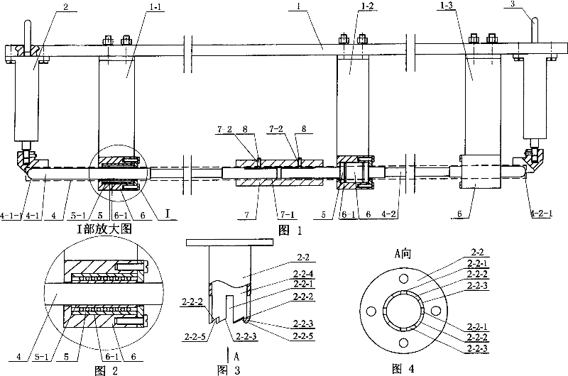
[0006] Specific embodiment 1: (see Fig. 1-Fig. 9) this embodiment is made up of lock bracket 1, front lock mechanism 2, rear lock mechanism 3 and linkage shaft 4, the upper end of front lock mechanism 2 is affixed to the front end of lock bracket 1 , the upper end of the rear lock mechanism 3 is affixed to the rear end of the lock bracket 1; the middle front, middle and middle rear of the lock bracket 1 are respectively fixed with a front bearing bracket 1-1, a middle bearing bracket 1-2 and a rear bearing The lower ends of the bracket 1-3, the front bearing bracket 1-1, the middle bearing bracket 1-2 and the rear bearing bracket 1-3 are respectively fixed with a linear bearing seat 6, and the three linear bearings 5 ​​are respectively placed on the three linear bearing seats 6 The inner hole 6-1 of the linkage shaft 4 is placed in the inner hole 5-1 of the cage of the three linear bearings 5, and the front end and the rear end of the linkage shaft 4 are connected with the lowe...

specific Embodiment approach 2

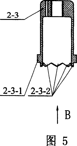
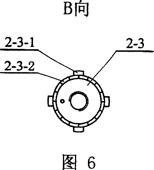
[0008] Specific embodiment two: (see Fig. 9) the difference between this embodiment and specific embodiment one is that the mechanical interlock mechanism also has a top screw 2-11, and the lower end of the shaft 2-6 is provided with an external thread 2-6 -3, the top surface of the top cone 2-8 has a connecting threaded hole 2-8-2, the side of the top cone 2-8 has a threaded hole 2-8-3, the lower end of the shaft 2-6 is connected to the top cone 2- The upper end of 8 is threaded, and jackscrew 2-11 is screwed in the threaded hole 2-8-3. Other compositions and connections are the same as in the first embodiment. An advantage of this embodiment is that the axial position of the top cone 2-8 relative to the shaft 2-6 is adjustable, which is convenient for installation and debugging.

specific Embodiment approach 3

[0009]Specific embodiment three: (see Fig. 1) The difference between this embodiment and specific embodiments one and two is that the mechanical interlock mechanism also has a coupling sleeve 7 and two jacking screws 8, and the coupling sleeve 7 is provided with an axial The through hole 7-1, the front part and the rear part of the side wall of the coupling sleeve 7 are respectively provided with radial threaded holes 7-2, and the two threaded holes 7-2 communicate with the axial through hole 7-1 respectively, and the linkage The shaft 4 is composed of the front shaft 4-1 and the rear shaft 4-2, the front end 4-1-1 of the front shaft 4-1 is a spherical surface, and the rear end of the front shaft 4-1 is placed in the axial through hole 7-1 The front part of the rear section shaft 4-2 is spherical, and the front end of the rear section shaft 4-2 is placed in the rear portion of the axial through hole 7-1, and two top screws 8 are rotated respectively. into two radially threaded...


PUM


Abstract

The invention relates to a design of mechanical interlock mechanism that includes two lock tool mechanism and a driving shaft. The front end and the back end of the supporting of the first lock tool mechanism separately connect to the up end of the front lock tool mechanism and the up end of the back lock tool mechanism. The middle front section, middle section and middle back section of the first lock tool supporting are separately set front shaft bearing, middle shaft bearing and back shaft bearing. The bottoms of the three shaft bearings are set three direct bearing. The driving shaft is set in the keeping hole of the three direct bearings. And the front end and the back end of the driving shaft are connected to the bottom of the front lock tool mechanism and the bottom point of the back lock tool mechanism, and realizing extending of the lock tools peak cone and driving the driving shaft to achieve the function of unlocking. The invention has good operation reliability and expansibility.

Description

Technical field: [0001] The invention relates to a mechanical interlock mechanism, in particular to a mechanical interlock mechanism for interior and exterior doors. Background technique: [0002] For some special occasions, such as the inner and outer doors of the isolation and intensive care unit for dangerous infectious diseases, in order to avoid the spread of germs caused by the entry and exit of personnel, the opening and closing of the two doors are required to be mutually self-locking and cannot be opened at the same time; the existing electromagnetic The application of the interlock mechanism is inconvenient in some occasions. At present, there is no mechanical interlocking mechanism with high reliability for interior and exterior doors. Invention content: [0003] In order to solve the problem of inconvenient application of the existing electromagnetic interlock mechanism on some occasions, the present invention provides a mechanical interlock mechanism, whose f...

Claims


Application Information

Patent Timeline
Patent Type & Authority Patents(China)
IPC IPC(8): E05C7/00E06B5/00
Inventor 高海波邓宗全陈明王忠奎刘吉成
Owner 山东严格产业发展有限公司
Why Eureka
Try Eureka