Blower

An air supply device and fan technology, which is applied to pump devices, components of pumping devices for elastic fluids, ventilation systems, etc., can solve problems such as inability to blow off, inability to supply air, and complicated operations, and reduce regular maintenance. The number of times, the effect of reducing maintenance costs

Inactive Publication Date: 2007-12-12
MITSUBISHI ELECTRIC CORP
View PDF4 Cites 0 Cited by
  • Summary
  • Abstract
  • Description
  • Claims
  • Application Information

AI Technical Summary

Problems solved by technology

[0007] However, when the blower is installed at a high place, it can be said that regular cleaning cannot be performed without scaffolding, so there are problems such as heavy labor and maintenance costs.
If a blower is installed in a place where regular maintenance is difficult, there may be problems such as clogging of the air inlet due to adhesion of dust, etc., resulting in failure of air supply
[0008] In addition, there is a problem that the blower that rotates the axial fan in reverse to clean the air inlet cannot completely blow off the dust in the center of the fan.
In addition, if the adhesion time of dust, etc. is too long, there is also a problem that the dust will stick to the filter or the protective cover and cannot be blown off.
[0009] With the blower device shown in Patent Document 1, although the air inlet can be cleaned, in order to remove the dust adhering to the filter, it is necessary to install a movable brush as another device, and there are problems such as cost.
In addition, because it is a movable mechanism, the maintenance of the brush itself is also a necessary issue.
[0010] In addition, in Patent Document 2, since the reverse operation of the axial flow fan needs to be performed manually, there is a problem that the operation is cumbersome.

Method used


Image

  • Blower
  • Blower

Examples


Embodiment approach 1

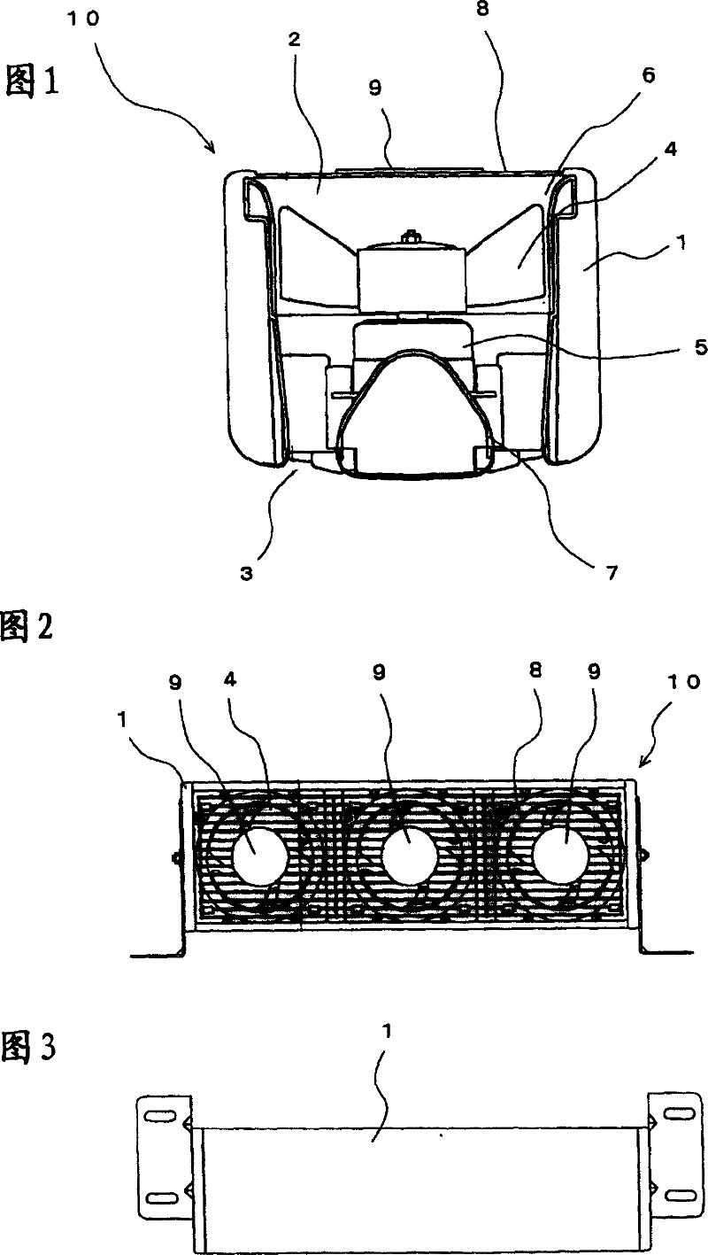
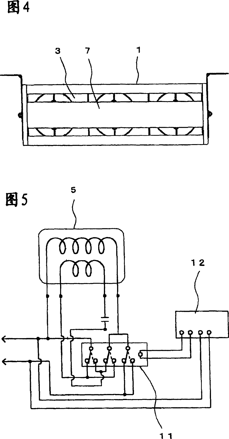
[0023] 1 is a cross-sectional view showing the internal structure of an air blower according to Embodiment 1 of the present invention, FIG. 2 is a rear view of an air blower equipped with, for example, three blowers of FIG. 1 , FIG. 3 is a top view of FIG. 2 , and FIG. Figure 2 Front view. FIG. 5 is a circuit diagram of this embodiment.

[0024] The air blower 10 is used for indoor air blowing or equipment cooling, and is installed in a state of being suspended, ground-mounted, or wall-mounted. The air blower 10 has a main body 1 in the shape of a six-sided box. The main body 1 is provided with an air inlet 2 at the back and an air outlet 3 at the front. In addition, the inside of the main body housing 1 is partitioned according to the number of air blowers. FIG. 1 shows one air blower, and FIG. 2 shows three air blowers. Moreover, each air blower inside the main body casing 1 is equipped with an axial flow fan 4 and a motor 5, and the axial flow fan is arranged in the insid...

Embodiment approach 2

[0033] In this embodiment, in the aspect of Embodiment 1, the timer switch 12 is used to make the air blower reversely operate only for a certain period of time at the start of the operation to perform cleaning. According to this, even if the power supply is turned off outside the operating hours, it is possible to clean the filter or the protective cover 8 .

Embodiment approach 3

[0035] In this embodiment, in the aspect of Embodiment 1, the timer switch 12 is used to make the air blower reversely run only for a certain period of time when the operation is finished, and to perform cleaning. According to this, even if the power supply is turned off outside the operating hours, it is possible to clean the filter or the protective cover 8 .


PUM


Abstract

The invention provides a blowing device capable of easily and automatically eliminating dust adhered to a filter or a protecting guard, in regard to a blower having a filter and a protecting guard in a suction opening thereof. This blowing device is provided with a main body box body 1 having the suction opening 2 on a back surface side and a blowing opening 3 on a front side thereof, a motor 5 provided inside the main body box body to normally and reversely rotate, an axial flow fan 4 fitted to a rotary shaft of the motor, and the filter or the protecting guard 8 fitted to the suction opening. A control circuit of the motor is provided with a switch means 11 for switching rotating direction of the motor to the opposite direction, and a time switch 12 for setting operating time of the switch means is provided. Reverse rotating operation is performed with a constant interval, and dust adhered to the filter or the protecting guard is blown off for cleaning.

Description

technical field [0001] The present invention relates to an air blower which has a filter or a protective cover at the air inlet and can easily remove dust adhering to the filter or protective cover. Background technique [0002] Among conventional air blowers, Patent Document 1 describes an air blower that cleans an air inlet. The air supply device is that a warm air channel is set between the air inlet on the back of the frame and the warm air outlet on the front, and a convection fan is installed near the air inlet to transport the indoor air from the air inlet to the warm air flow path, changing In such a heater, a filter is installed on the back of the convection fan, and a movable brush connected to it is installed on the outside of the filter. When cleaning the filter, it is driven by the driving member. The brush is activated to make the convection fan reverse to remove the dust adhering to the filter with the brush, and blow it away with the wind of the convection f...

Claims


Application Information

Patent Timeline
Patent Type & Authority Patents(China)
IPC IPC(8): F24F11/02F24F7/00F04D29/70F04D27/00F04D25/10F04D29/00
Inventor 小林茂己桔功下村和幸荻野泰隆
Owner MITSUBISHI ELECTRIC CORP
Why Eureka
Try Eureka