Welding slag removing device for high-frequency welding machine

A high-frequency welding machine and welding slag technology, which is applied in the direction of high-frequency current welding equipment, auxiliary equipment, welding equipment, etc., can solve the problem of affecting the quality and efficiency of metal welding, damaging the welding joints of high-frequency welding machines, and easily damaging high-frequency welding Machine and other problems to achieve the effect of improving operational safety, improving welding quality and efficiency, and reducing operational difficulty

Inactive Publication Date: 2021-04-02
温州市扬铃贸易有限公司
View PDF0 Cites 0 Cited by
  • Summary
  • Abstract
  • Description
  • Claims
  • Application Information

AI Technical Summary

Problems solved by technology

[0005] Aiming at the deficiencies of the prior art, the present invention provides a device for removing welding slag from high-frequency welding machines, which has the advantages of automatic cleaning, simple cleaning of welding slag, not easy to damage the welding machine, and safety, and solves the existing high-frequency welding machine welding slag removal device. The welding machine is used for metal welding and after a period of use, the welding part of the high-frequency welding machine will attach a large amount of metal welding slag, which will not only affect the quality and efficiency of metal welding, but also damage the welding joints of the high-frequency welding machine At the same time, the existence of welding slag is likely to bring a certain risk of high temperature burns to the operator during the welding process. The existing treatment method is processed by manual use of tools. Manual operation is difficult to clean, and the cleaning process will easily damage the high-frequency Problems with welding machine parts

Method used


Image

  • Welding slag removing device for high-frequency welding machine
  • Welding slag removing device for high-frequency welding machine
  • Welding slag removing device for high-frequency welding machine

Examples


Embodiment Construction

[0024] The following will clearly and completely describe the technical solutions in the embodiments of the present invention with reference to the accompanying drawings in the embodiments of the present invention. Obviously, the described embodiments are only some, not all, embodiments of the present invention. Based on the embodiments of the present invention, all other embodiments obtained by persons of ordinary skill in the art without making creative efforts belong to the protection scope of the present invention.

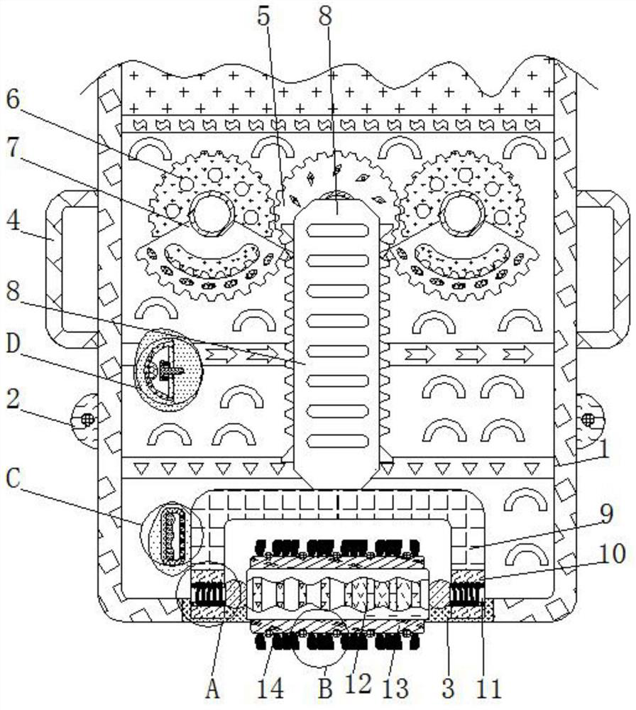
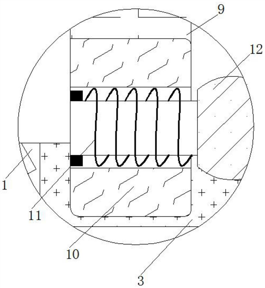
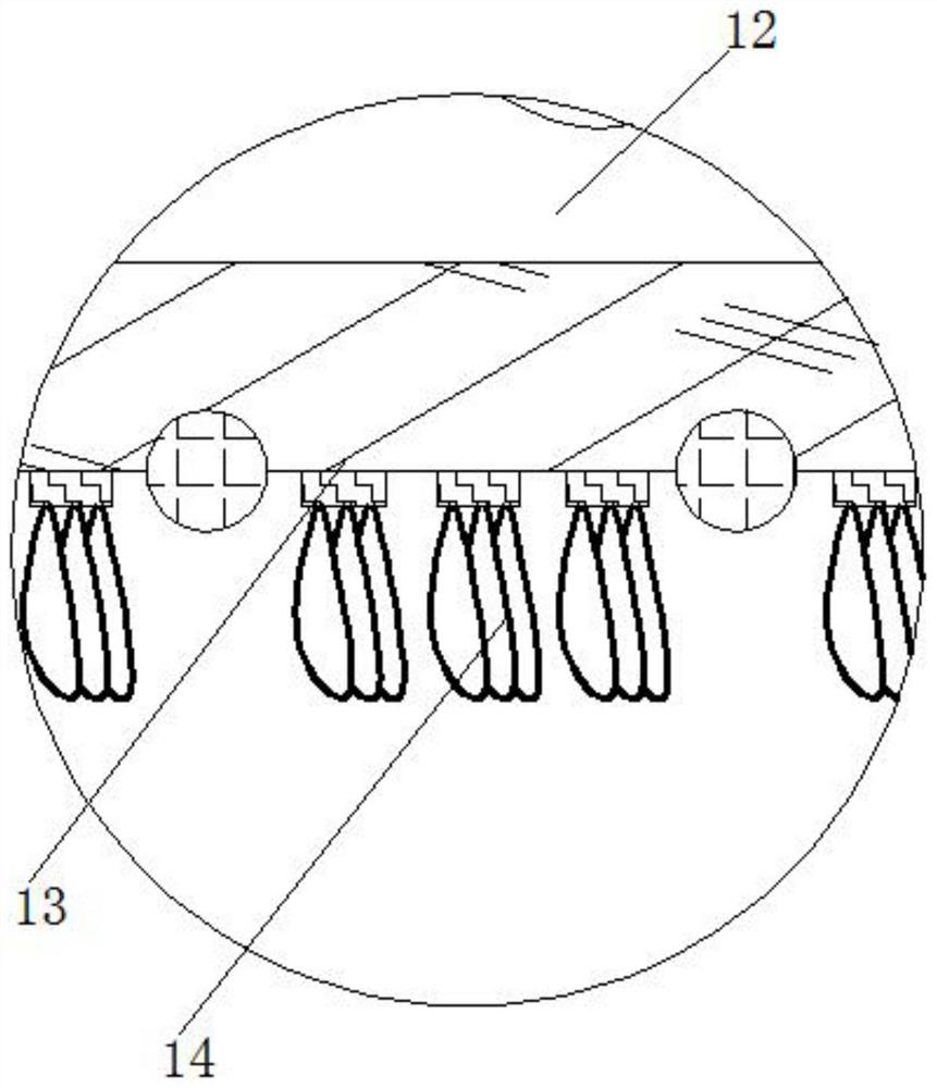
[0025] see Figure 1-5 , a device for removing welding slag from a high-frequency welding machine, comprising a casing 1, a button 2 is fixedly connected to the outside of the casing 1, a cleaning port 3 is opened on the surface of the casing 1, an operating rod 4 is fixedly connected to the outside of the casing 1, The surface of the casing 1 is provided with a light opening, the number of which is not less than twenty, and all the light openings are evenly d...


PUM


Abstract

The invention relates to the technical field of high-frequency welding machines, and discloses a welding slag removing device for a high-frequency welding machine. The welding slag removing device comprises a shell, a button is fixedly connected to the exterior of the shell, a cleaning opening is formed in the surface of the shell, an operating rod is fixedly connected to the exterior of the shell, and a first gear is movably connected to the interior of the shell; and a second gear is movably connected to the interior of the shell, and a sector gear is fixedly connected to the exterior of thesecond gear. Under the interaction of a cleaning opening, the operating rod, the first gear, the second gear, the sector gear, a rack, a supporting plate, a U-shaped magnetic plate, an electromagnet,a rotating shaft, a fastening plate, a friction brush, a photosensitive assembly and a detection assembly, an operator can be prevented from being scalded by high-temperature welding slag in the welding process of the high-frequency welding machine, and the operation safety of the high-frequency welding machine is improved; and meanwhile, the operation difficulty of the welding machine is also reduced, so that the welding speed can be increased in actual welding operation, and the project completion speed is increased.

Description

technical field [0001] The invention relates to the technical field of high-frequency welding machines, in particular to a device for removing welding slag from high-frequency welding machines. Background technique [0002] High-frequency welding machine is different from other welding machines. Its function and use are not just single welding. It has the characteristics of fast heating speed, high efficiency, and instant melting of any metal objects. The welding of metal materials can also be used for diathermy, smelting, heat treatment and other processes. It is suitable for heat treatment quenching, annealing, metal diathermy forging, extrusion molding, solder welding, etc. The existing high-frequency welding machine is used for metal welding And after a period of use, the welding parts of the high-frequency welding machine will be attached to a large amount of metal welding slag, which will not only affect the quality and efficiency of metal welding, but also damage the ...

Claims


Application Information

Patent Timeline
Patent Type & Authority Applications(China)
IPC IPC(8): B23K13/00B23K37/00
CPCB23K13/00B23K37/00
Inventor 阳金华
Owner 温州市扬铃贸易有限公司
Why Eureka
Try Eureka