Refrigerator

A technology for refrigerators and coolers, used in defrosting, household appliances, refrigeration and liquefaction, etc., can solve problems such as leakage, control circuit board influence, and not considering the expansion and contraction of insulating materials.

Active Publication Date: 2007-12-19
HITACHI GLOBAL LIFE SOLUTIONS INC
View PDF8 Cites 0 Cited by
  • Summary
  • Abstract
  • Description
  • Claims
  • Application Information

AI Technical Summary

Problems solved by technology

During defrosting operation, the temperature of the heating wire will reach hundreds of degrees, but it does not consider the expansion and contraction of the insulating material under such a large temperature change.
[0020] In addition, in Patent Document 2, there are fins for promoting heat dissipation on the outer circumference of the armored tube. However, when the armored tube is broken, the heating wire inside the armored tube hangs down and comes into contact with the water tank. Causes leakage and has the disadvantage of badly affecting the control circuit board

Method used


Image

  • Refrigerator
  • Refrigerator
  • Refrigerator

Examples


Embodiment 1

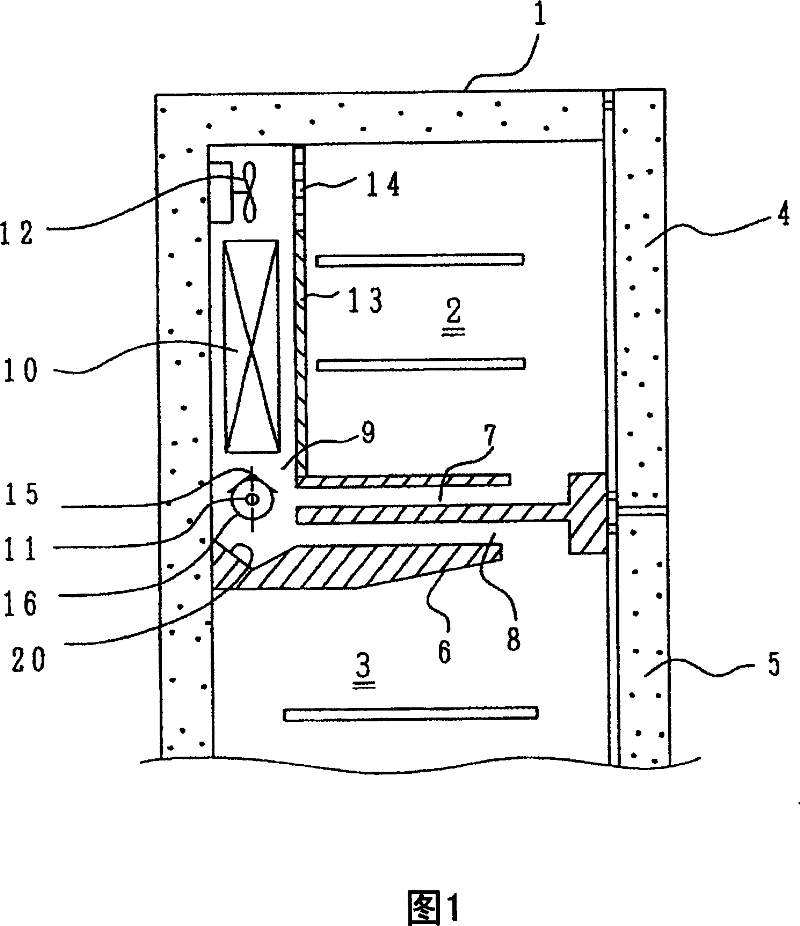
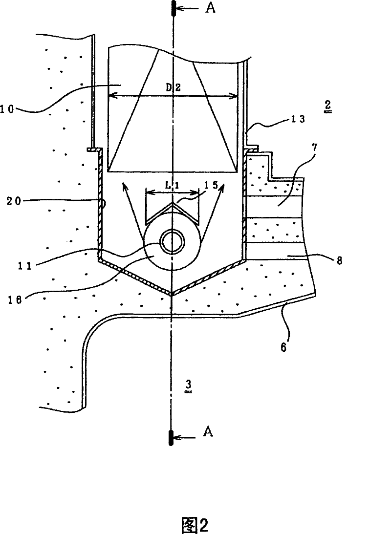
[0052] First, the structure of the refrigerator will be described using FIGS. 1 to 4 . The refrigerator main body 1 has a freezer compartment 2 and a refrigerator compartment 3 inside it. In front of the freezer compartment 2 there is a freezer door 4 for closing the opening, and in front of the refrigerator compartment 3 there is a refrigerator door 5 for closing the opening. Between the freezing chamber 2 and the refrigerating chamber 3, there is an intermediate partition 6 which separates the two chambers. The duct 7 that goes to the cooler described later, and the duct 8 that returns the cold air after heat exchange with the food in the refrigerating chamber 3 to the cooler.

[0053] At the back of the freezer compartment 2, a cooler compartment 9 partitioned by a partition 13 is arranged. In this cooler compartment 9, a cooler 10, a defrosting heater 11, and a cooling air circulation fan 12 are provided. In this embodiment, the defrosting heater 11 is arranged below the...

Embodiment 2

[0073] Next, Example 2 will be described using FIG. 5 and FIG. 6 .

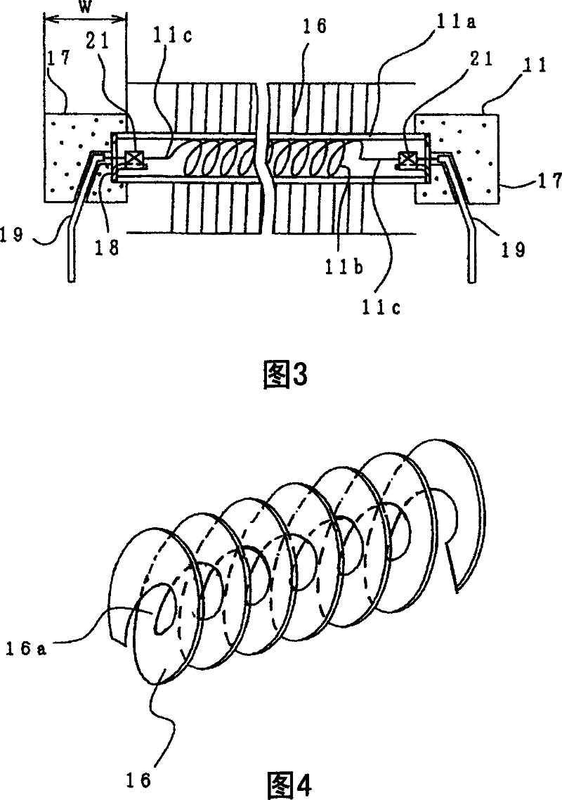
[0074] First, in FIG. 5, the reference numeral 17 is a rubber plug, the reference numeral 16 is a cooling fin, and the reference numeral 11a is a glass tube. One end face in the width direction of the above-mentioned heat dissipation fin 16 is wound to perpendicularly intersect with the glass tube 11a. In order to absorb the difference in natural curvature, a diameter-reduction is provided near the inner side of the above-mentioned heat dissipation fin (on the side of the glass tube). Part 16c, and the side opposite to the glass tube is made into a plane.

[0075] As shown in the figure, the cooling fins 16 are wound around the glass tube 11 a between the rubber plugs 17 . In other words, the cooling fins 16 are provided over the entire length of the glass tube 11a between the rubber plugs at both ends of the glass tube 11a.

[0076] Reference numeral 16b is a bent portion provided at the winding start and ...

Embodiment 3

[0086] Next, a third embodiment of the present invention will be described using FIGS. 7 to 9 .

[0087] In the figure, the numeral 10 is a cooler, the numeral 11 is a defrosting heater, the numeral 11a is a glass tube, the numeral 11b is a heating wire, the numeral 15 is an upper cover, the numeral 15a is a fixed part of the upper cover 15, and the numeral 15b is each The connecting part where the fixed parts are connected, the number 16 is the heat dissipation fin, the number 17 is the rubber plug, the number 20 is the water tank, the number 20a is the water outlet of the water tank, the number 20b is the metal plate (aluminum plate) for heating the water tank, and the number 19 is Reference numeral 20c is a support leg for supporting the heater for defrosting on the water tank 20 as a lead wire for supplying power to the heating wire 11b.

[0088] In FIG. 8 , the upper cover 15 is close to or in contact with the cooling fins 16 . The upper cover 15 is close to or in contac...


PUM


Abstract

The invention solves a problem found when a glass tube is broken that a heater wire in the glass tube hangs and is brought into contact with a trough, which causes electric leakage and has harmful effects on a control board or the like. This refrigerator comprises a cooler, a defrosting heater mounted on a lower part of the cooler for removing frost attached to the cooler, a heat radiating member mounted on an outer periphery of the defrosting heater, the trough mounted on a lower part of the defrosting heater for receiving defrost water dropped from the cooler, and an upper cover mounted on an upper part of the defrosting heater for protecting the defrosting heater from the defrost water dropped from the cooler. The defrosting heater has the glass tube, the heater wire incorporated in the glass tube and rubber plugs for sealing both ends of the glass tube, and both ends of the upper cover are fixed to the rubber plugs.

Description

technical field [0001] The present invention relates to a refrigerator having a defrosting heater for removing frost adhering to a cooler of a refrigerating cycle. Background technique [0002] As a prior art related to a refrigerator equipped with a defrosting heater, for example, there is a refrigerator described in Patent Document 1 - Japanese Patent Application Laid-Open No. 8-54172. In this example, a tubular heater for defrosting, in which nickel-chrome wire is wound into a coil and wrapped with a glass tube, is installed below the cooler. This tubular heater for defrosting removes frost adhering to the cooler. An upper cover covering the defrosting tubular heater is provided between the cooler and the defrosting tubular heater to prevent defrosting water dripping from the cooler from directly contacting the defrosting tubular heater. In addition, between the tubular heater for defrosting and the water tank below it, a bottom edge for maintaining electrical insulatio...

Claims


Application Information

Patent Timeline
Patent Type & Authority Patents(China)
IPC IPC(8): F25D21/08
CPCF25B2400/12F25D21/08F25D23/028F25D2321/1413F25D2321/143F25D2321/1441H05B3/44
Inventor 加纳奖一广田明久荒川贤一
Owner HITACHI GLOBAL LIFE SOLUTIONS INC
Why Eureka
Try Eureka