

Light source module
A technology of light source modules and components, applied in the direction of light source, electric light source, electroluminescent light source, etc., can solve the problem of uneven brightness, and achieve the effect of improving bright lines and improving brightness
- Summary
- Abstract
- Description
- Claims
- Application Information
AI Technical Summary
Problems solved by technology
Method used
Image

Examples
no. 1 example
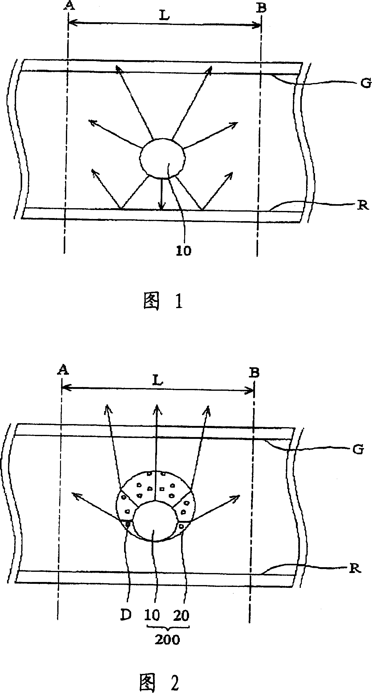
[0017] Next, please refer to FIG. 2 , which shows a schematic view of the first embodiment of the present invention. As shown in the figure, the light source module of the present invention is suitable for a flat panel display, and includes a lamp assembly 200 , a reflector R and a diffuser G. The lamp assembly 200 includes a lamp 10 and a light-transmitting element 20 , and the lamp 10 is a cold cathode lamp (CCFL) disposed between the reflector R and the diffuser G. The surface of the reflector R is provided with a reflective material to reflect light. In addition, a panel (not shown) is arranged above the diffuser G for displaying images.
[0018] Generally speaking, a plurality of lamp tubes 10 arranged in parallel can also be set in the light source module, wherein the light emitted by the lamp tubes 10 can be reflected by the reflector R and pass through the diffuser G, or directly pass through the diffuser G and emit upwards. , to provide the brightness required by a f...
no. 2 example
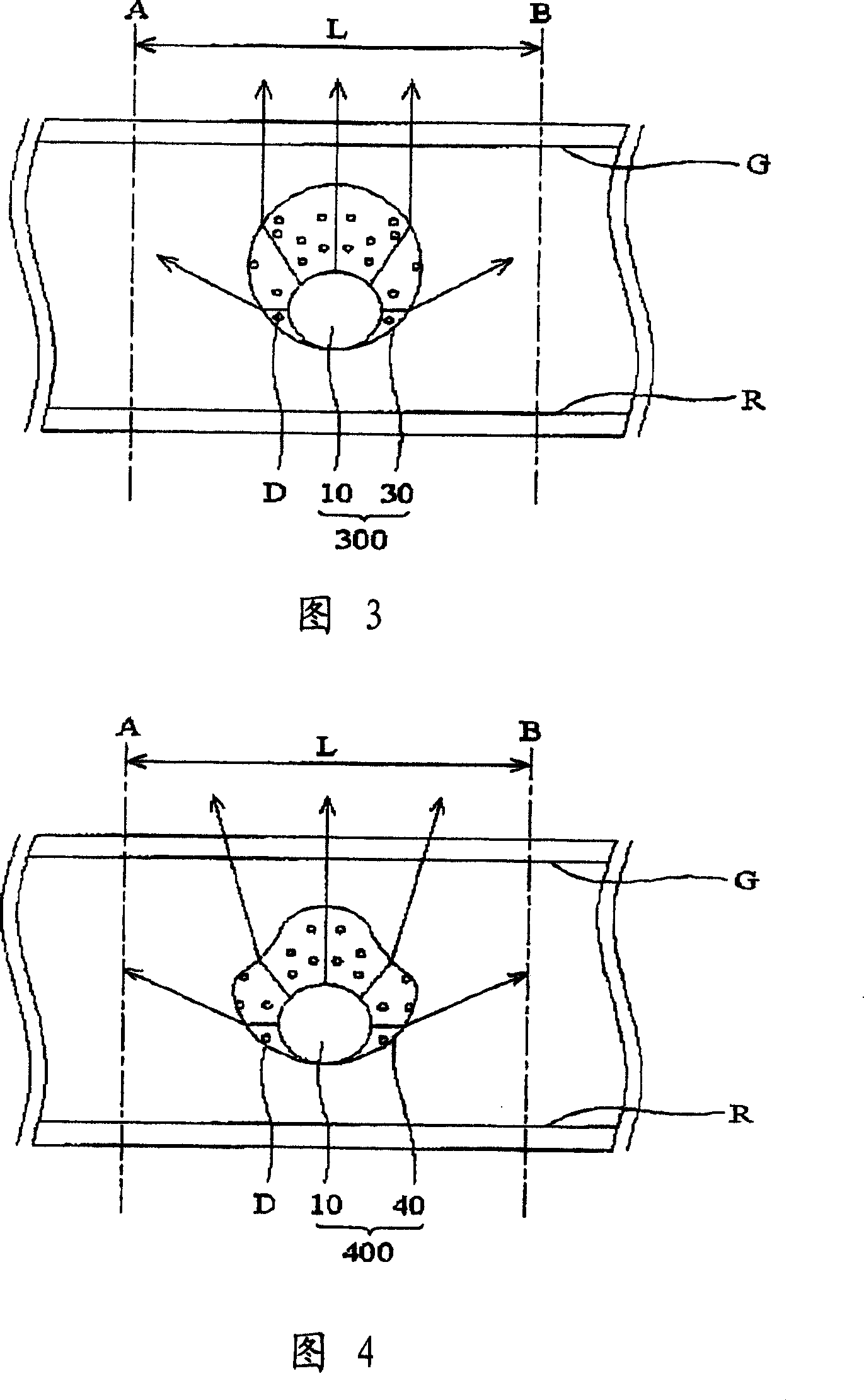
[0024] Next, please refer to FIG. 3 , which shows a schematic diagram of a second embodiment of the present invention. As shown in the figure, the light source module of the present invention is suitable for a flat panel display, and includes a lamp assembly 300 , a reflector R and a diffuser G. The lamp assembly 300 includes a lamp 10 and a light-transmitting element 30 , and the lamp 10 is a cold cathode lamp (CCFL) disposed between the reflector R and the diffuser G. Generally speaking, a plurality of lamp tubes 10 arranged in parallel can also be set in the light source module, wherein the light emitted by the lamp tubes 10 can be reflected by the reflector R and pass through the diffuser G, or directly pass through the diffuser G and emit upwards. , to provide the brightness required by a flat panel display (such as a liquid crystal flat panel display).
[0025] In the present invention, an elliptical light-transmitting element 30 is sheathed outside the lamp tube 10 , w...
no. 3 example
[0030] Next please refer to FIG. 4 , which shows a schematic diagram of a third embodiment of the present invention. As shown in the figure, the light source module of the present invention is suitable for a flat panel display, and includes a lamp assembly 400 , a reflector R and a diffuser G. The lamp assembly 400 includes a lamp 10 and a light-transmitting element 40 , and the lamp 10 is a cold cathode lamp (CCFL) disposed between the reflector R and the diffuser G. Generally speaking, a plurality of lamp tubes 10 arranged in parallel can also be set in the light source module, wherein the light emitted by the lamp tubes 10 can be reflected by the reflector R and pass through the diffuser G, or directly pass through the diffuser G and emit upwards. , to provide the brightness required by a flat panel display (such as a liquid crystal flat panel display).
[0031]In the present invention, an irregular light-transmitting element 40 is sheathed outside the lamp tube 10 , where...
PUM
 Abstract
Description
Claims
Application Information