Backlight module

A backlight module and light pipe technology, applied in optics, nonlinear optics, instruments, etc., can solve the problem that the backlight module cannot transmit light to the shooting object, and achieve the effect of increasing the intensity of reflected light

Inactive Publication Date: 2008-03-26
HONG FU JIN PRECISION IND (SHENZHEN) CO LTD +1
View PDF7 Cites 0 Cited by
  • Summary
  • Abstract
  • Description
  • Claims
  • Application Information

AI Technical Summary

Problems solved by technology

[0006] In order to overcome the problem that the backlight module in the prior art cannot transmit light to the object to be photographed, the present invention provides a backlight module that can transmit light to the object to be photographed
[0008] In order to overcome the problem that the backlight module in the prior art cannot transmit light to the object to be photographed, the present invention provides another backlight module that can transmit light to the object to be photographed

Method used


Image

  • Backlight module
  • Backlight module
  • Backlight module

Examples


Embodiment Construction

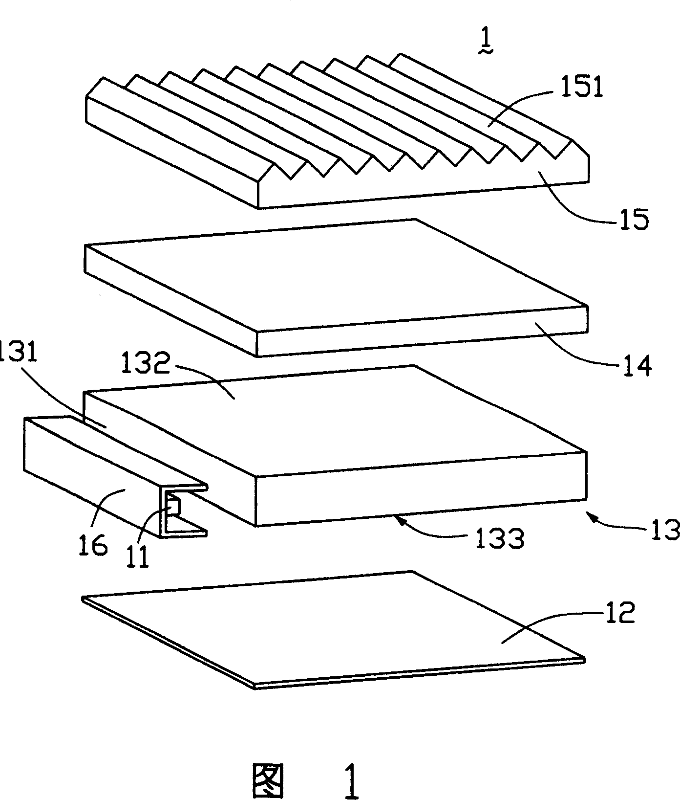
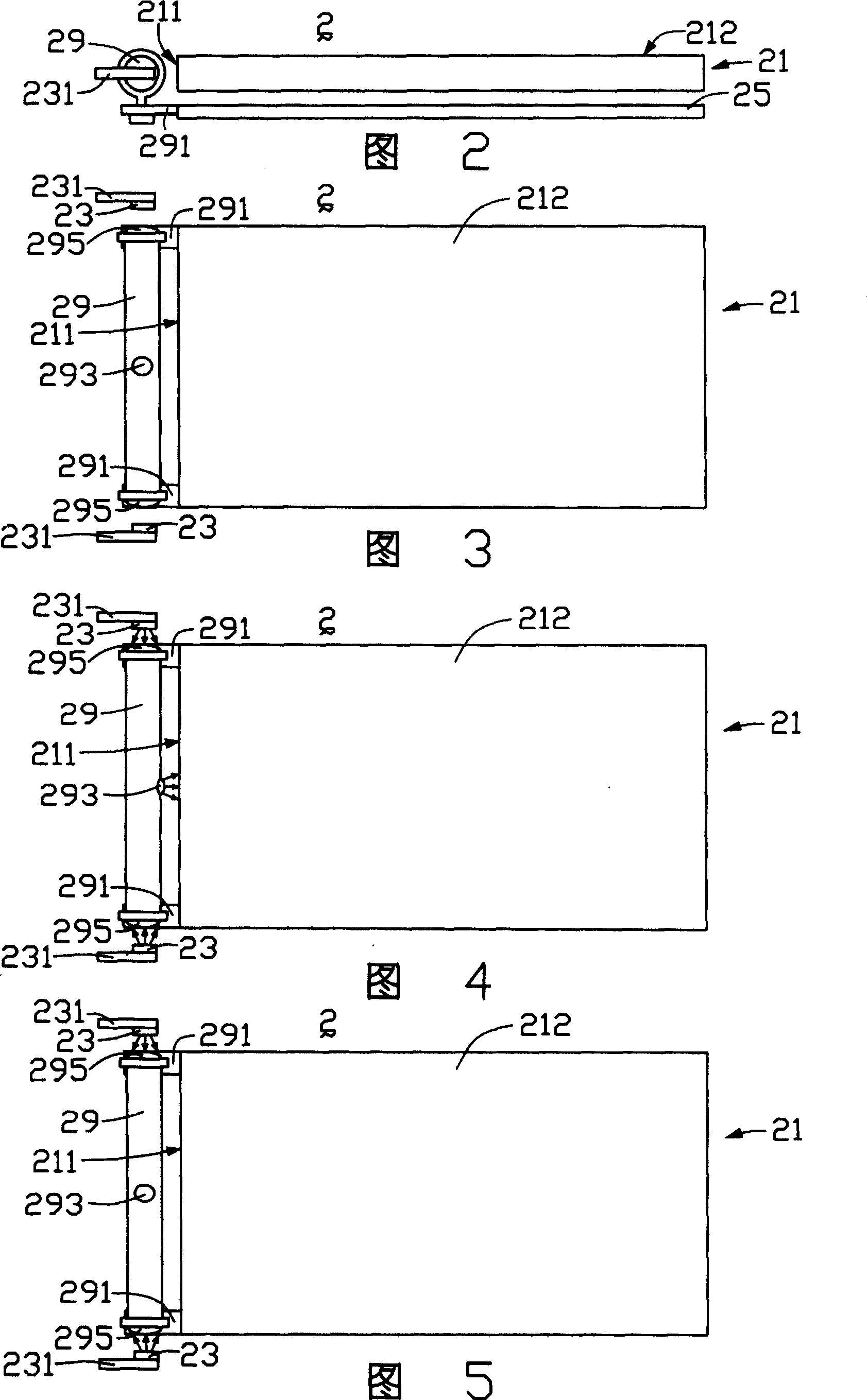
[0018] Please refer to FIG. 2 and FIG. 3 together, which are respectively a front view and a top view of the first embodiment of the backlight module of the present invention. The backlight module 2 includes a light guide plate 21 , two point light sources 23 , a light guide pipe 29 and a substrate 25 .

[0019] The light guide plate 21 includes a light incident surface 211 and a light exit surface 212 , the light exit surface 212 and the light incident surface 211 are perpendicular to each other. The light pipe 29 is disposed on one side of the light incident surface 211 and has a rotating mechanism 291 at both ends thereof. The base plate 25 is arranged under the light guide plate 21 , and is connected with the rotating mechanism 291 to fix the light guide pipe 29 . The two point light sources 23 are arranged on one side of the light incident surface 211 , and are respectively located at two ends of the light pipe 29 , and the point light sources 23 are connected to the dri...


PUM


Abstract

The invention relates to a phototropic mold train, which comprises a light inlet side. The light source is positioned on one side of light inlet side of the light driving plate. The phototropic mold train also comprises a rotated light-driving pipe which is positioned on one side of light inlet side and which comprises a light inlet end and a light outlet end. The light outlet end transmits the light form light source to the advanced direction.

Description

【Technical field】 [0001] The invention relates to a backlight module, in particular to a backlight module for digital image products. 【Background technique】 [0002] Since the liquid crystal in the panel of the liquid crystal display device cannot emit light itself, in order to achieve the display effect, it is necessary to provide a light source device, such as a backlight module, for the panel of the liquid crystal display device. The function of the backlight module is to provide planar light with sufficient brightness and uniform distribution to the panel of the liquid crystal display device, so that it can display images normally, and thus becomes one of the key components of the liquid crystal display device. [0003] With the continuous expansion of the application field of liquid crystal display devices, especially the application of digital imaging products, such as mobile phones, digital cameras for mobile phones, digital video cameras, etc., the requirements for b...

Claims


Application Information

Patent Timeline
Patent Type & Authority Patents(China)
IPC IPC(8): G02F1/13357G02F1/133G02F1/1335
Inventor 张仁淙
Owner HONG FU JIN PRECISION IND (SHENZHEN) CO LTD
Why Eureka
Try Eureka