Tableware cleaning drier

A tableware cleaning and drying machine technology, which is applied in the direction of tableware washing machine/rinsing and washing machine parts, etc., can solve the problems of knocking down/breaking, etc., and achieve the effect of improving operability, increasing torque, and alleviating wire deterioration

Inactive Publication Date: 2008-07-09
PANASONIC CORP
View PDF2 Cites 0 Cited by
  • Summary
  • Abstract
  • Description
  • Claims
  • Application Information

AI Technical Summary

Problems solved by technology

If you accidentally touch glass and ceramic containers in order to operate, it is also very likely that they will be knocked over / broken

Method used


Image

  • Tableware cleaning drier
  • Tableware cleaning drier
  • Tableware cleaning drier

Examples


Embodiment Construction

[0027] Embodiments of the present invention are described below with reference to the drawings.

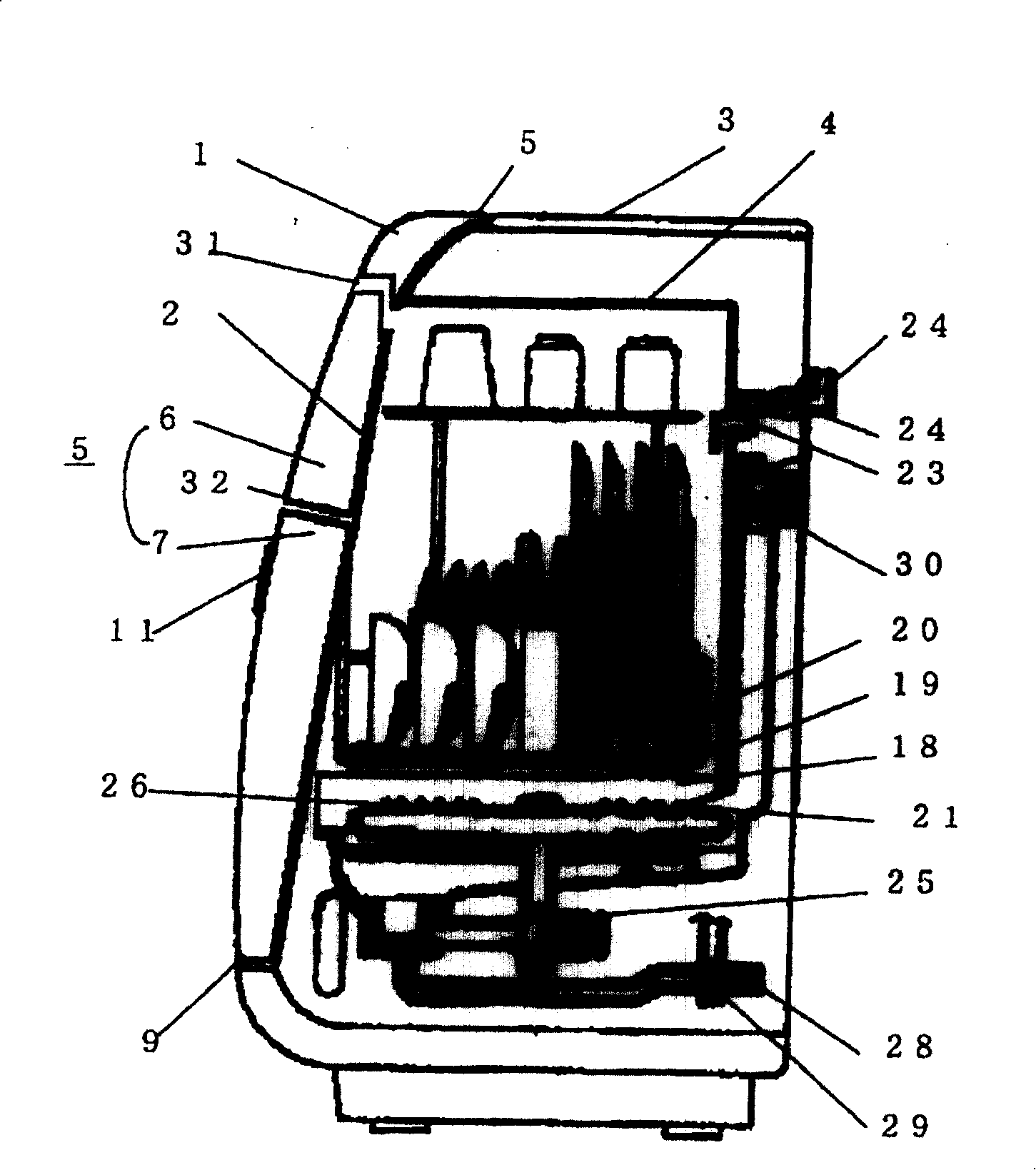
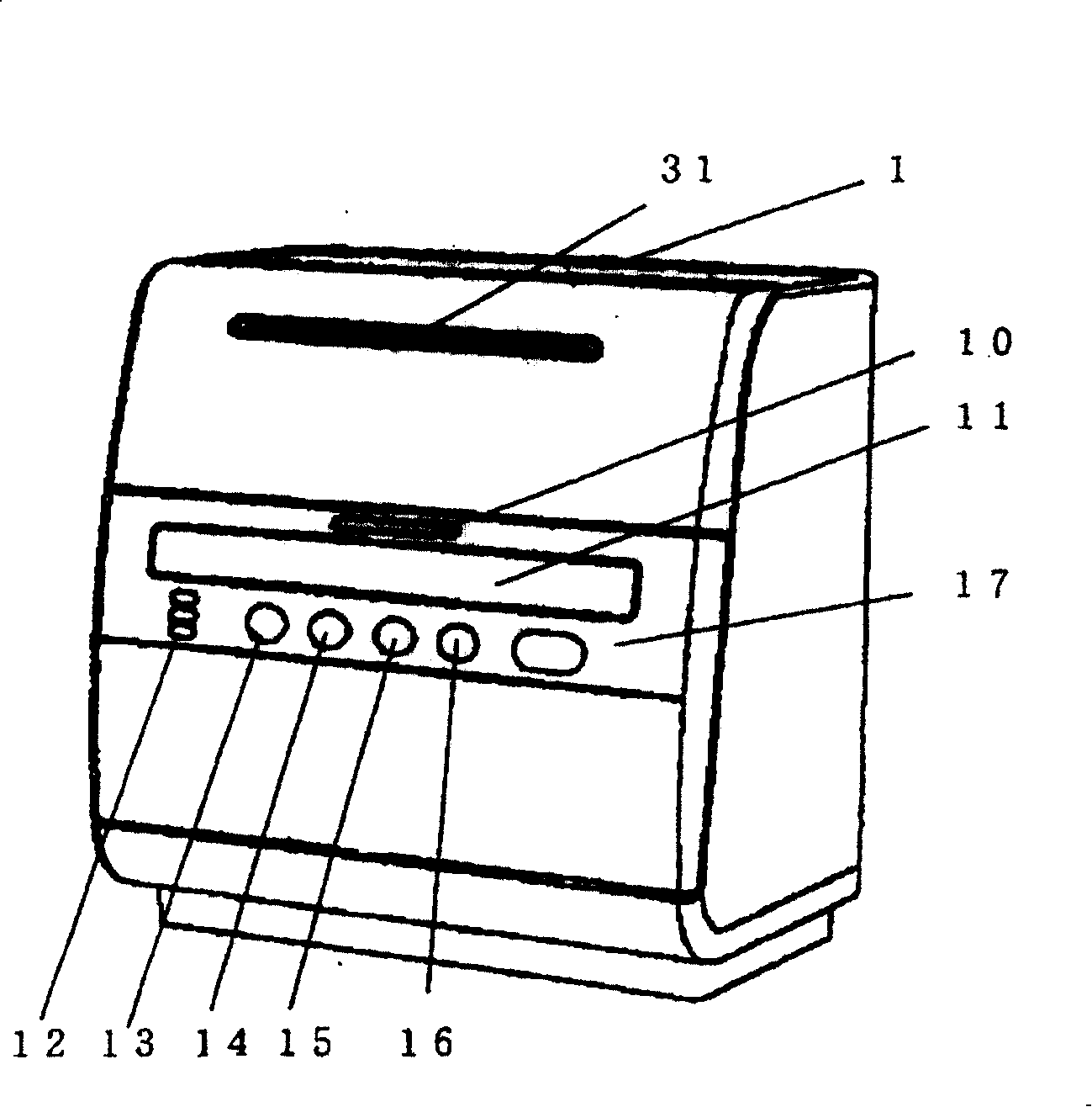
[0028] Such as figure 1 As shown in , the body 1 is provided with an outer tank 3 , and the inside of the outer tank 3 is provided with a cleaning chamber 4 . In addition, the front part of the outer tank 3 is provided with an opening 2, and the opening 2 is provided with a door 5 which can be freely opened and closed.

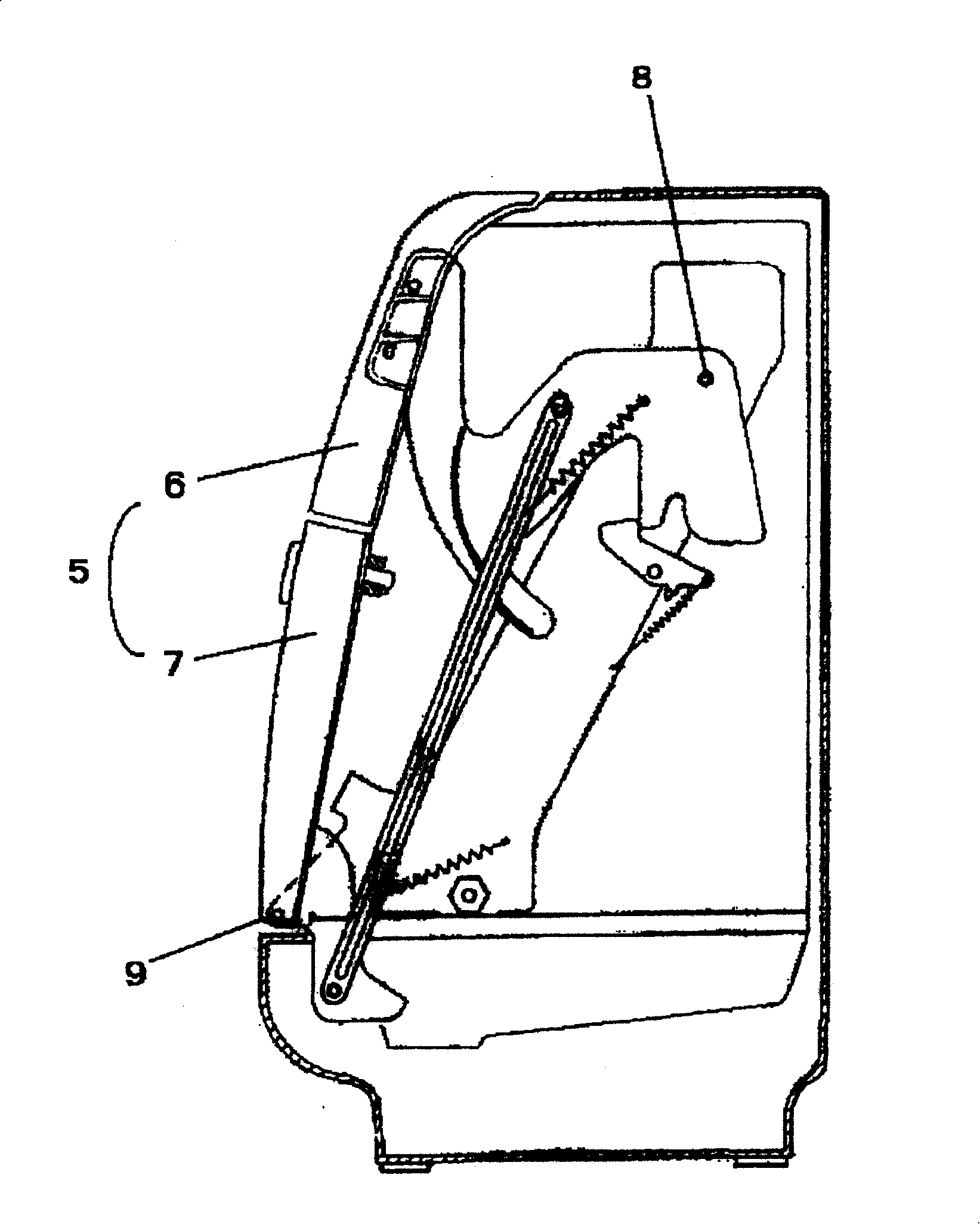
[0029] Machine door 5 is made up of upper door body 6 and lower door body 7, and these two door bodies 6,7 are respectively installed on the rotating shaft device 8,9 that is located on opening 2, up and down, can open and close freely up and down.

[0030] In addition, by adopting devices such as a link mechanism, each door body 6, 7 can be opened and closed simultaneously in an interlocking manner, and their closed state is locked by a locking device not shown in the figure.

[0031] Such as figure 2 As shown in , the lower door body 7 is sequentially provid...


PUM


Abstract

The objective is to improve the operability and visibility of an operation display part in a dish washing and drying machine. A door is constituted of upper and lower door bodies. Also, on the upper part of the lower door body, a closing operation part 10, an unlocking operation body 11 for unlocking the closing lock of a lid,the operation display part 17 constituted of a course display part 12, a course switching button 13, a drying time switching button 14, a temporary stop button 15 and a power ON / OFF button 16 in the order from the top is provided. Thus, handling is performed all at the same place, and not only the operability is improved but also it is made easy to see from a user.

Description

technical field [0001] The invention relates to a tableware washing and drying machine used in common households and professional places. Background technique [0002] In the conventional dish washer and dryer of this type, the front opening of the washing chamber can be freely opened / closed by the machine door. [0003] In addition, a dish basket that slides on rails with wheels is provided inside the washing room to facilitate pulling out / pushing in, and a plurality of washing nozzles provided around the dish basket spray washing water on objects to be washed. [0004] After the cleaning is completed, the cleaning water is discharged to the outside through the drain pump, and then the drying operation is performed by warm air or the like. [0005] The cleaning pump, drainage pump, etc. are controlled by the control device located under the cleaning chamber, and the user operates through the operation display device provided with a power switch and a start switch below the...

Claims


Application Information

Patent Timeline
Patent Type & Authority Patents(China)
IPC IPC(8): A47L15/48A47L15/46A47L15/42
Inventor 角谷胜彦田中淳裕新海清恭
Owner PANASONIC CORP
Why Eureka
Try Eureka