Eureka AIR delivers breakthrough ideas for toughest innovation challenges, trusted by R&D personnel around the world.

Method and device for demagnetizing body

A technology for demagnetizing objects, applied in the direction of magnetic objects, electrical components, circuits, etc.

Inactive Publication Date: 2008-08-06
阿尔贝特・莫伊雷尔
View PDF6 Cites 0 Cited by
  • Summary
  • Abstract
  • Description
  • Claims
  • Application Information

AI Technical Summary

Problems solved by technology

However, other interfering factors must be taken into account, such as the actual residual magnetic

Method used


Image

  • Method and device for demagnetizing body
  • Method and device for demagnetizing body
  • Method and device for demagnetizing body

Examples


Embodiment Construction

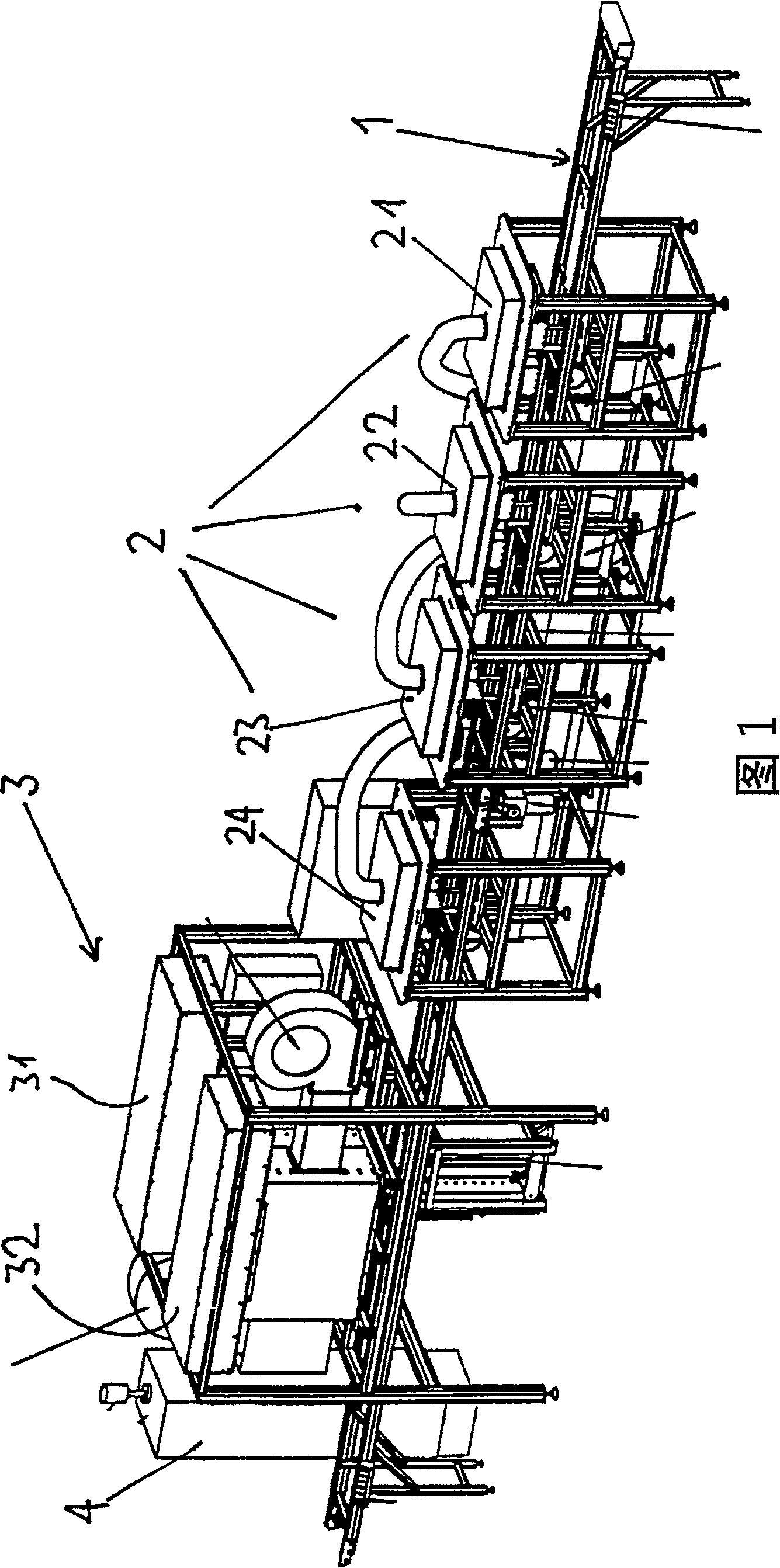
[0015] The basis and basic concept of the method according to the invention will be described below. It is assumed that a screen or a shadow mask of the screen as a whole with associated frames and extensions are typical objects to be degaussed. This shadow mask is here only as a prime example of such an object.

[0016] The method of degaussing is carried out in two separate steps. First, magnetized hard points in the shadow mask, such as weld seams, pressure points, etc., are pretreated locally at high fields by means of choke coils in an alternating field. As a result, these magnetized hard points are at least partially demagnetized.

[0017] In a decisive second step according to the invention, the entire system, in this case the shadow mask with the associated frame and extension parts as a whole, is completely degaussed. Instead of the shadow mask being attracted by an alternating magnetic field according to the prior art, the shadow mask is held locally in a magnetic...


PUM


Abstract

A demagnetizing method of the invention includes two separated steps. First, preprocessing magnetizing hard parts of demagnetizing objects such as welding seam, pressure parts in local of high field by choking coil of alternating field. Through the step at least partly demagnetizing these magnetizing hard parts. Then, completely demagnetizing in the second critical step. The object is stationary in magnetism alternating field a period. With gradually degression of the magnetism alternating field, electrically controlling the coil relative to frequency and amplitude.

Description

technical field [0001] The present invention relates to methods and devices for degaussing objects. Background technique [0002] Known methods of degaussing objects use an open core with a coil through which a constant alternating current flows. Apply the core to the object and turn on the AC. The core is then slowly moved away from the object manually. This degaussing process is greatly influenced by the surrounding environment and cannot be reproduced exactly. This degaussing is incomplete and not always as good. [0003] Using another known method, it is possible to operate with a coil tunnel with a large coil through which the alternating current flows. Attracts objects through a coil tunnel with a stable magnetic field. With this method, the object is first subjected to an increasing magnetic field and then a decreasing magnetic field. The degaussing effect is limited to a single direction. [0004] With the materials of mechanical components used today and the ...

Claims


Application Information

Patent Timeline
Patent Type & Authority Patents(China)
IPC IPC(8): H01F13/00
CPCH01F13/006
Inventor 阿尔贝特·莫伊雷尔乌尔斯·迈耶
Owner 阿尔贝特・莫伊雷尔
Why Eureka
Eureka Blog
Learn More