

Full wave rectification circuit
A full-wave rectification circuit and circuit technology, applied to electrical components, AC power input conversion to DC power output, irreversible AC power input conversion to DC power output, etc., to achieve good circuit adaptability, simple circuit, and reduce input The effect of reactive power
- Summary
- Abstract
- Description
- Claims
- Application Information
AI Technical Summary
Problems solved by technology
Method used
Image

Examples
Embodiment 1
[0025] Embodiment 1: In the full-wave rectification circuit proposed by the present invention, the DC converter (1) works in the BOOST circuit mode in one half cycle, and works in the CUK circuit mode in the other half cycle. As shown in Figure 4, in this example, a rectifier bridge is formed by the first to four rectifier diodes (D3, D4, D5, D6); Output diodes (D1, D2), energy storage capacitors (C1), output filter capacitors (C2) and output filter inductors (L2); the anode of the first output diode D1 is connected to the cathode of the full-wave rectifier bridge BR1, and the first The cathode of an output diode D1 is connected to the positive pole of the filter capacitor C2; the energy storage capacitor C1 is connected between the anode output terminal of the full-wave rectifier bridge BR1 and the cathode of the second output diode D2; the anode of the second output diode D2 is connected to On the negative pole of the filter capacitor C2, energy is provided to the output in ...
Embodiment 2
[0029] Embodiment two: if Figure 7 As shown, the basic working principle is similar to the previous description, and the difference from Embodiment 1 is that in the positive half cycle, the second output diode (D2) is turned on, and the diodes in the upper left corner and lower right corner of the full-wave rectifier bridge BR1 are turned on at this time , work in CUK mode, negative half cycle, the first output diode (D1) conduction, at this time the upper right corner and lower left corner of the full-wave rectifier bridge BR1 conduction, work in BOOST mode. Because CUK output and input polarity are reversed, BOOST output is the same polarity, so the output voltage of negative polarity can be obtained.
Embodiment 3
[0030] Embodiment three: as Figure 8 As shown, the difference from Embodiment 1 is that it uses two switch tubes instead of one, and the rectifier diode is reduced to two.
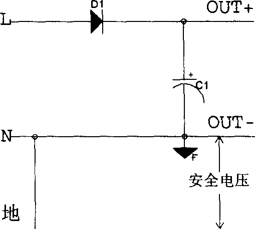
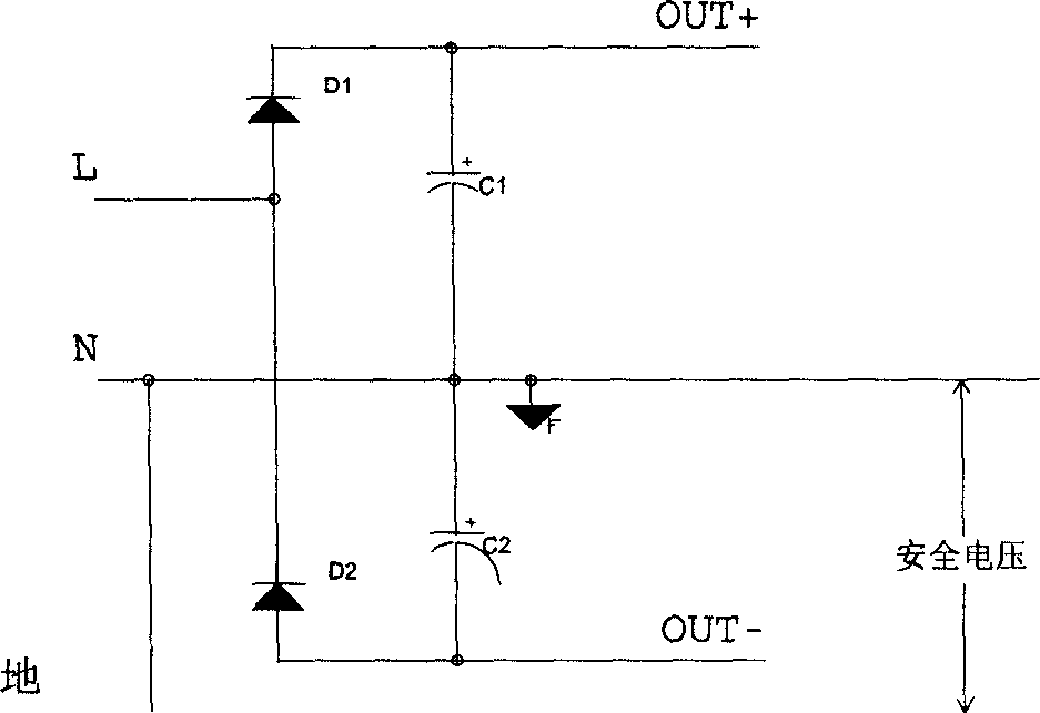
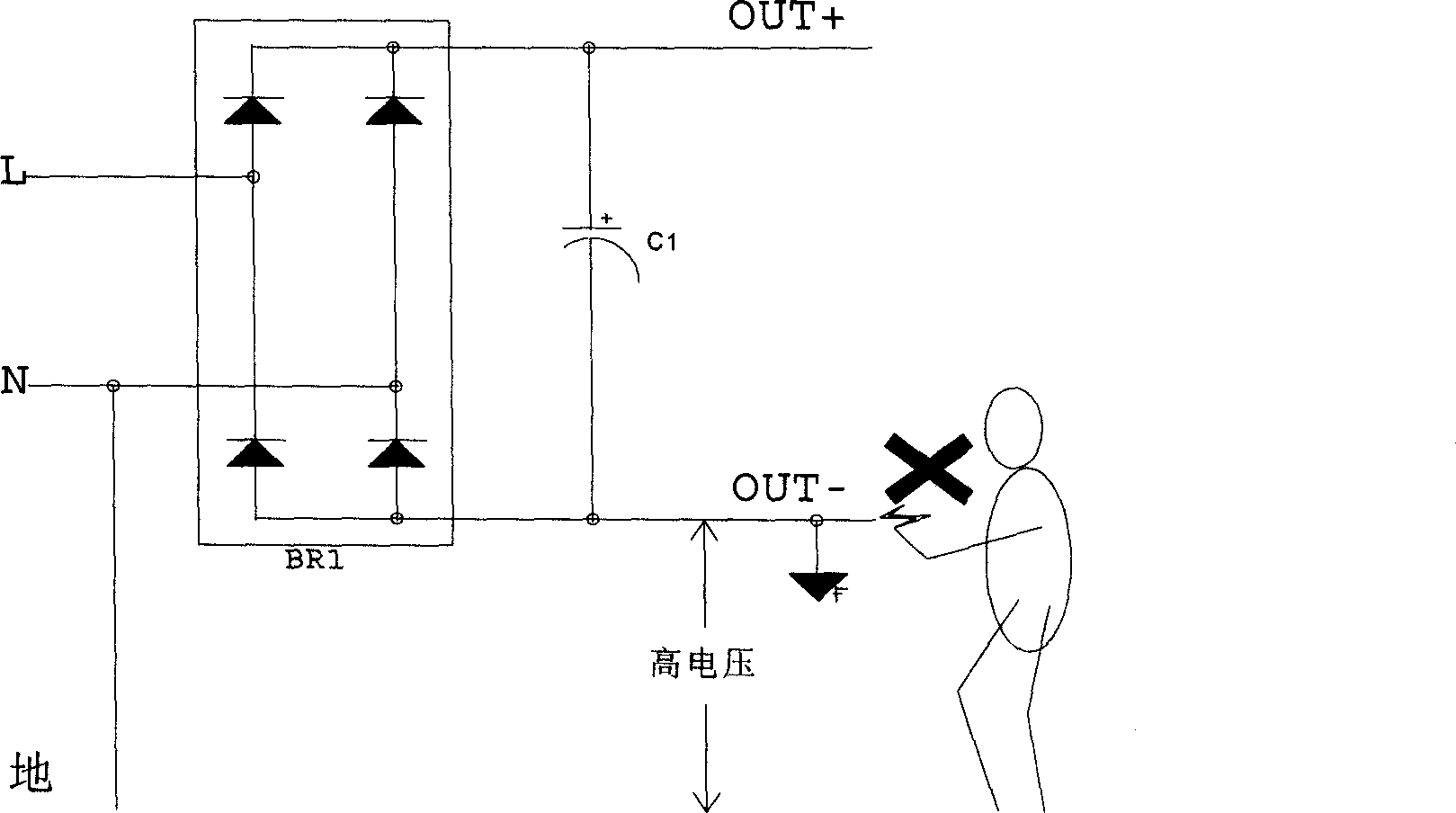
[0031] The full-wave rectification circuit can effectively overcome various shortcomings of the previous circuit. That is, the input and output neutral lines are connected, and the output end is not suspended from the ground, so there is no danger of electric shock; the positive and negative half cycles of the input can work, and the input current can be symmetrical; the output voltage can be a set of voltages, and there is no need to consider the problem of load balance; since the output is a safe voltage, There is no need for an isolation circuit; the circuit is simple, and only one switch tube is needed. Various other converters can also be added behind the rectifier circuit to obtain the desired power supply as required. If a special control circuit is added, the power factor correction (PFC) functi...
PUM
 Abstract
Description
Claims
Application Information