
Method for making fluid dynamic simulation process flow

A technology of process flow and dynamic simulation, applied in educational appliances, instruments, identification devices, etc., can solve the problems of idle LED display screen, unable to fully display the process links, difficult to use units, etc., which is conducive to long-term continuous operation and display. Full-featured, easy-to-create effects

Inactive Publication Date: 2008-08-27
张月山
View PDF6 Cites 0 Cited by
  • Summary
  • Abstract
  • Description
  • Claims
  • Application Information

AI Technical Summary

Problems solved by technology

Using LED display as a dynamic simulation process plate, although it has a strong display function, also has obvious shortcomings: first, the cost is high, and the general user unit cannot bear it; second, the resolution is low and the text is small The instructions and some subtle process links cannot be fully displayed; the third is that in addition to the process, there is still a considerable area of ​​the LED display screen that has been idle for a long time, resulting in objective waste

Method used


Image

  • Method for making fluid dynamic simulation process flow
  • Method for making fluid dynamic simulation process flow
  • Method for making fluid dynamic simulation process flow

Examples


Embodiment Construction

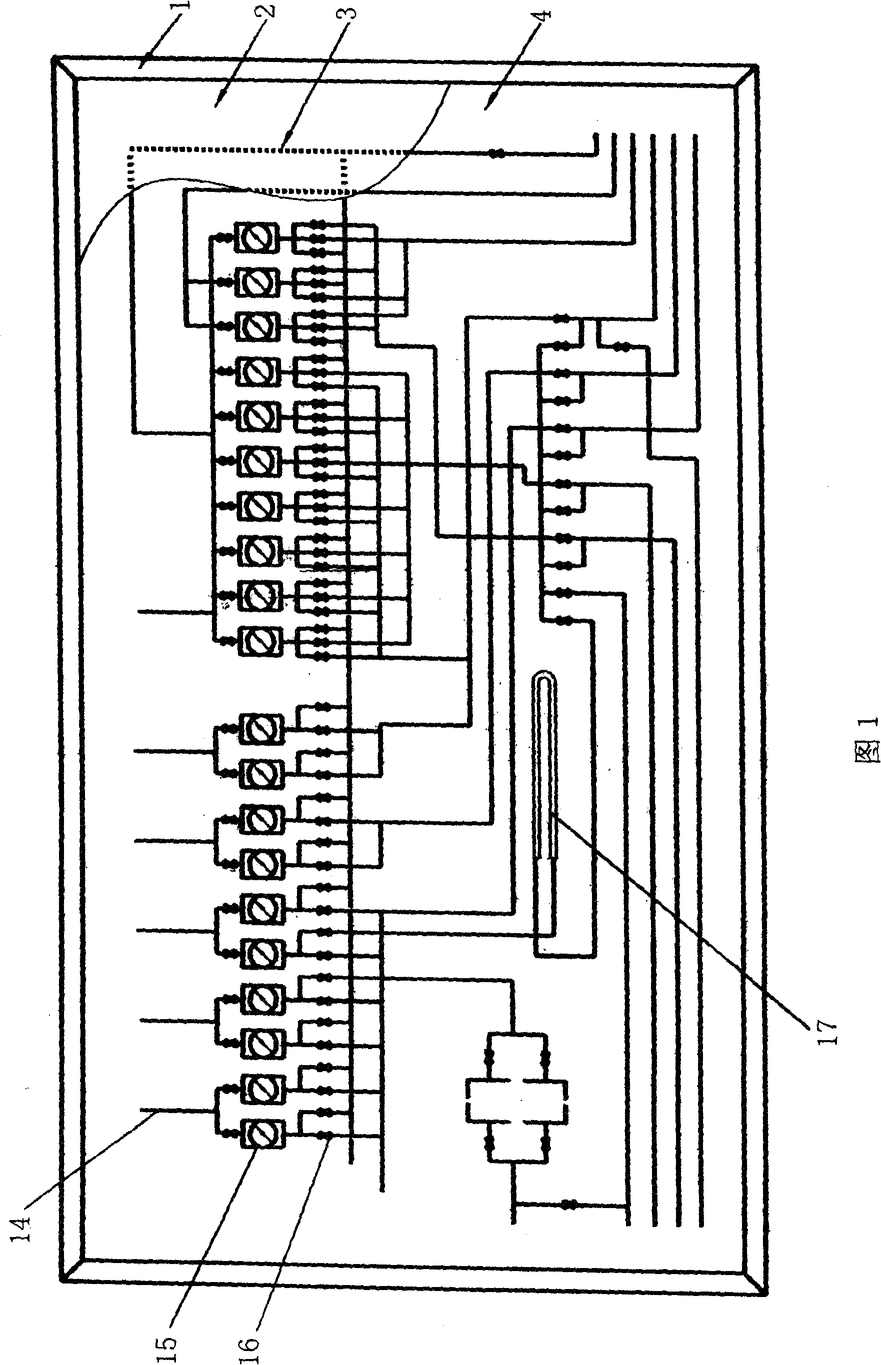
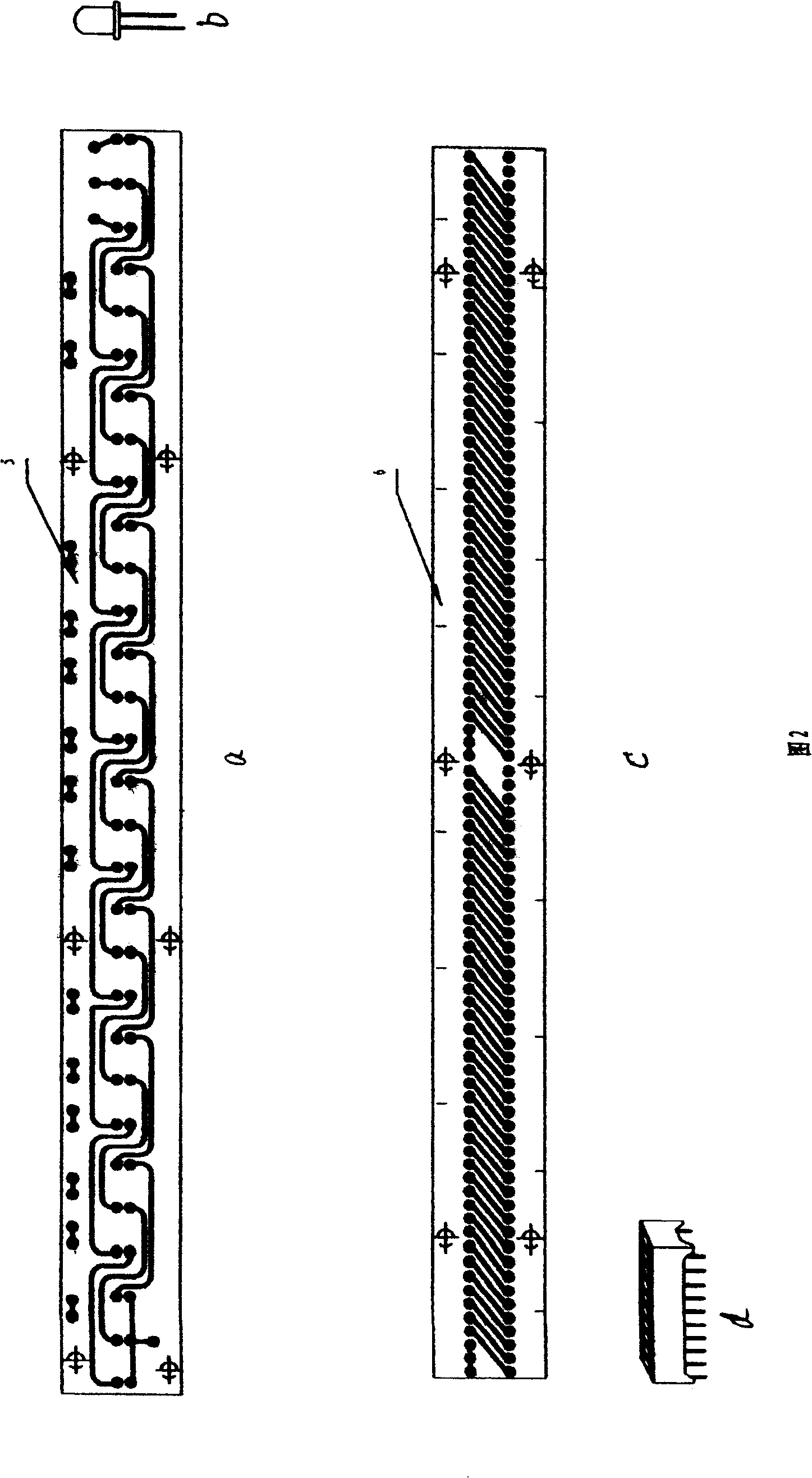
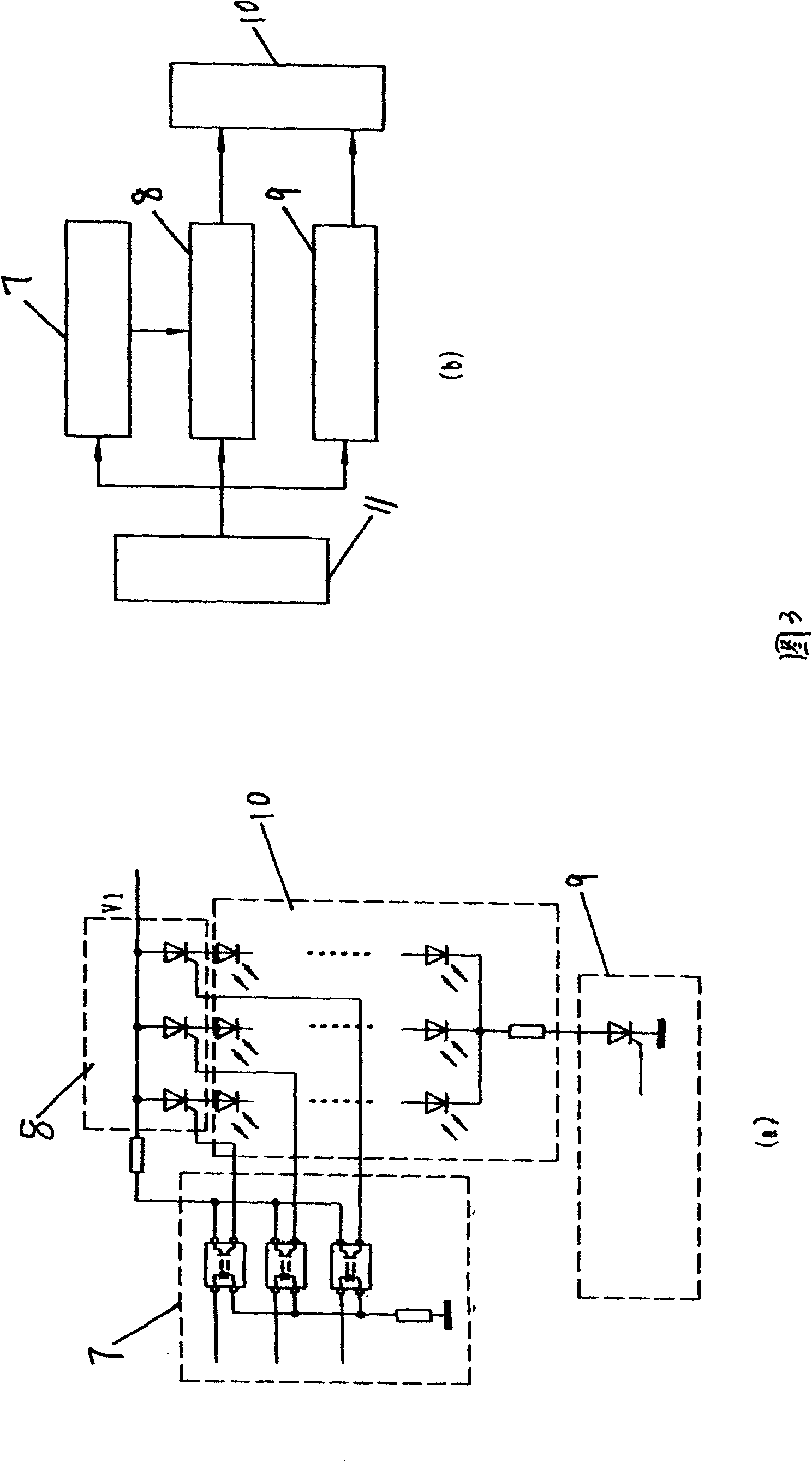
[0028] In order to further disclose the technical solutions of the present invention, the following will be described in detail through examples in conjunction with the accompanying drawings:

[0029] 1. The luminous bar assembly 3 adopts light-emitting diodes and semi-integrated LED luminous columns, which are respectively welded to the printed circuit boards 5 and 6 (see Figure 2) to display the process pipeline 14, flow meter 15, valve 16 and standard The working state of volume tube 17. The graphics of the flowmeter 15 and the standard volume tube 17 adopt light-emitting diode (see Figure 2b) components, first drill holes along the graphics on the substrate, and the hole distance is equal to the distance between the light-emitting tubes. 14. Use the luminous column (see Figure 2d) assembly, first groove on the substrate along the process, the groove width is equal to the width of the luminous column, and the end surface of the luminous column is flush with the surface of t...


PUM


Abstract

A method for flow process making on fluid dynamic simulation, is made from frame, placode, luminous banding assembly, hasp veil, light emitting diode, printed circuit board, luminous pole printed circuit board, control circuit and electrical source, the characteristic is to weld the light emitting diode or half integration LED luminous pole on the printed circuit board, corresponding to the flow process inserting superposed on placode, the upper surface of light emitting diode or half integration LED luminous pole and the placode surface are in the same horizontal plane, which covers with the veil made from advertising lamp box sheet and painted with flow process to make the flow process on veil and on the light emitting diode or half integration LED luminous pole reclose correspondently, and then inserts the veil and placode together with solid frame.

Description

1. Technical field [0001] The invention relates to a production method for simulating and displaying fluid flow conditions and controlled positions in a process flow and expressing working principles by using circuits and electronic components on a display panel. Specifically, it is a method for making a fluid dynamic simulation process flow. 2. Background technology [0002] The simulated process panel is based on the traditional process flow chart to demonstrate the process flow and express the working principle in a static or dynamic way. Because the static simulation process board basically does not deviate from the traditional process flow chart mode, it is rarely used in some places with high requirements. Using LED display as a dynamic simulation process plate, although it has a strong display function, also has obvious shortcomings: first, the cost is high, and the general user unit cannot bear it; second, the resolution is low and the text is small The instruction...

Claims


Application Information

Patent Timeline
Patent Type & Authority Patents(China)
IPC IPC(8): G09F9/33G09B19/00
Inventor 张月山刘希会
Owner 张月山
Learn More