Lubricating structure for closed compressor baffle plate

A technology of lubricating structure and compressor, applied in rotary piston machinery, rotary piston/oscillating piston pump parts, mechanical equipment, etc., can solve the problem of compressor function decline, compressor reputation decline, and electric component input force increase. And other issues

Inactive Publication Date: 2008-11-19
LG ELECTRONICS (TIANJIN) APPLIANCES CO LTD
View PDF6 Cites 2 Cited by
  • Summary
  • Abstract
  • Description
  • Claims
  • Application Information

AI Technical Summary

Problems solved by technology

[0009] However, in the existing hermetic compressor, since each baffle plate 5A, 5B is in close contact with the gap between the baffle plate slots 3c, 3d, the above-mentioned baffle plate 5A, 5B is in contact with the baffle plate when it moves back and forth up and down. Plate grooves 3c, 3d create friction
As a result, the input force of the electric parts will increase, which will cause a problem that the function of the compressor will decrease.
There is also a problem that the credibility of the compressor is reduced when the compressor is used for a long time due to friction between the baffles 5A, 5B and the baffle grooves 3c, 3d.

Method used


Image

  • Lubricating structure for closed compressor baffle plate
  • Lubricating structure for closed compressor baffle plate
  • Lubricating structure for closed compressor baffle plate

Examples


Embodiment Construction

[0025] Hereinafter, preferred embodiments according to the present invention will be described in detail with reference to the accompanying drawings.

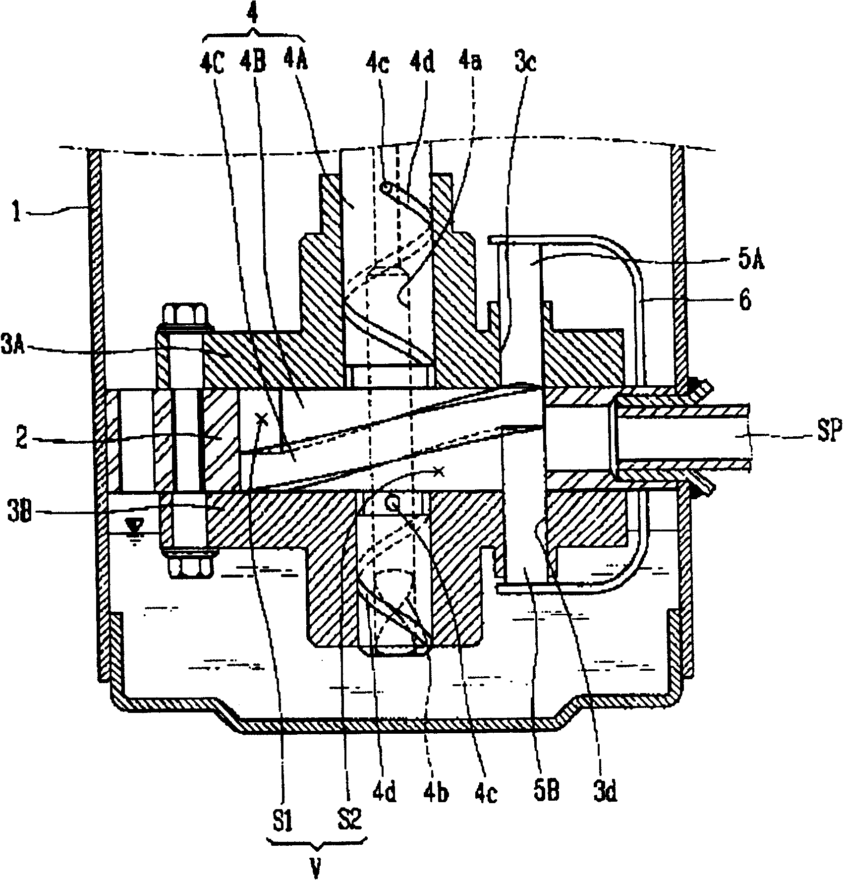
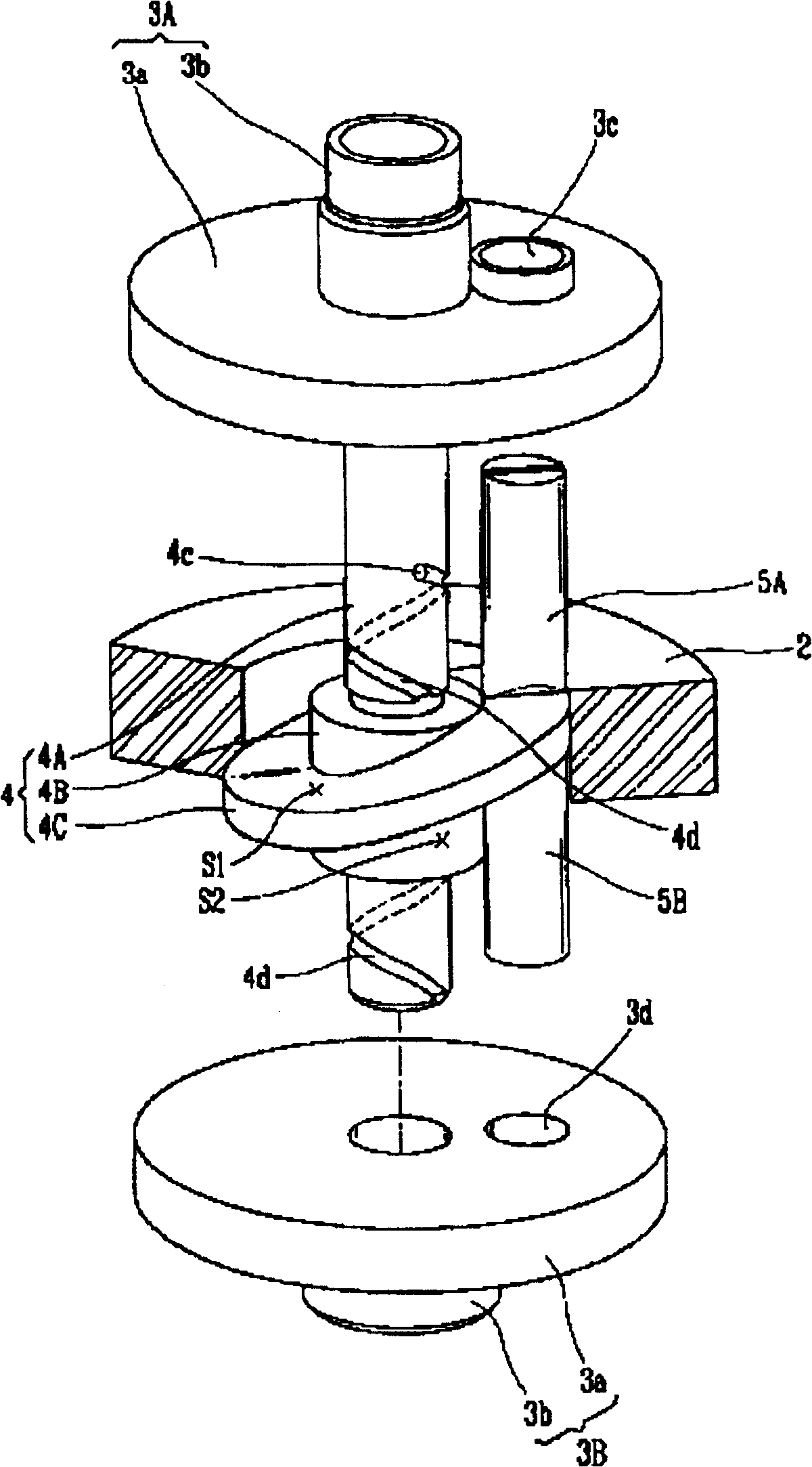
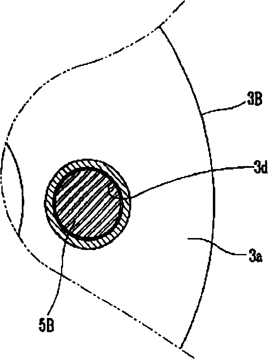
[0026] Figure 4 It is a partial cross-sectional schematic diagram of the hermetic compressor provided by the present invention. Figure 5 and Figure 6 It is a longitudinal sectional view and a schematic plan view of the compression parts in the hermetic compressor provided by the present invention. Figure 7 is along Figure 6 The cross-sectional view made by the I-I line in . The compression member is constituted by the air cylinder 12 , the first bearing plate 13A, the second bearing plate 13B, the rotating shaft 14 , the first flap 15A, the second flap 15B, and the flap spring 16 . Wherein, the cylinder 12 is fixed on the lower half of the shell 11, and its inside is provided with an inner space V for compressing refrigerant gas; the first bearing panel 13A and the second bearing panel 13B are mounted on the upper and ...


PUM


Abstract

The present invention relates to one kind of baffle lubricating structure for sealed compressor. The sealed compressor of the present invention includes cylinder, bearing panel, rotating shaft and baffle. Lubricating oil feeding hole is formed from the outside of the compression chamber of bearing panel to the inside of the baffle. By means of the pressure difference between the inside and the outside of the compression chamber, lubricating oil flows through the feeding hole into baffle slot to reduce friction between the baffle and other part. The present invention can reduce input power of the electric part, improve the functions of the compressor, reduce friction between parts and raise the reliability of the compressor.

Description

technical field [0001] The invention relates to a hermetic compressor which divides the internal space of the cylinder into several compression chambers; in particular, to a hermetic compressor which reduces the friction between the baffle and the slot of the baffle and the friction of the baffle to improve the efficiency of the motor Baffle lubrication structure (VANE LUBRICATION STRUCTURE FOR VANECOMPRESSOR). Background technique [0002] Ordinary hermetic compressors divide the internal space of the cylinder into a suction space and a compression space by sticking and pressing a baffle on the rotating body. At the same time, the suction space and the compression space are continuously replaced by rotating the rotating body, so as to carry out the processes of suction, compression, and discharge of the oil body. [0003] figure 1 It is a longitudinal sectional view of a hermetic compressor in the prior art. As shown in the figure, a conventional compressor generally inc...

Claims


Application Information

Patent Timeline
Patent Type & Authority Patents(China)
IPC IPC(8): F04C29/02F04C18/00
Inventor 李胜俊
Owner LG ELECTRONICS (TIANJIN) APPLIANCES CO LTD
Why Eureka
Try Eureka