Wet mud burning treatment apparatus with compound dryer

A technology of a composite dryer and treatment device, which is applied to the oxidation treatment of sludge, incinerators, combustion methods, etc., can solve the problems of high cost of harmless treatment, complicated sludge incineration system, and large energy consumption of drying equipment, etc. To achieve the effect of simplifying the dry incineration treatment process, strengthening heat transfer, and saving operating costs

Active Publication Date: 2008-12-31
INST OF ENGINEERING THERMOPHYSICS - CHINESE ACAD OF SCI
View PDF10 Cites 1 Cited by
  • Summary
  • Abstract
  • Description
  • Claims
  • Application Information

AI Technical Summary

Problems solved by technology

However, most of the existing sludge incineration methods require the use of special equipment to dry the sludge before incineration. The drying and incineration are completed in two sets of equipment, and the system is complicated; the drying equipment consumes a lot of energy. , high operating costs and high safety requirements; and simple incineration of dry sludge is easy to produce NOx, so a denitrification device needs to be installed after the incinerator; at the same time, due to the sulfur content in the sludge, a desulfurization device needs to be equipped after the incinerator
This makes the sludge incineration system complicated and the cost of harmless treatment high

Method used


Image

  • Wet mud burning treatment apparatus with compound dryer
  • Wet mud burning treatment apparatus with compound dryer
  • Wet mud burning treatment apparatus with compound dryer

Examples


Embodiment 1

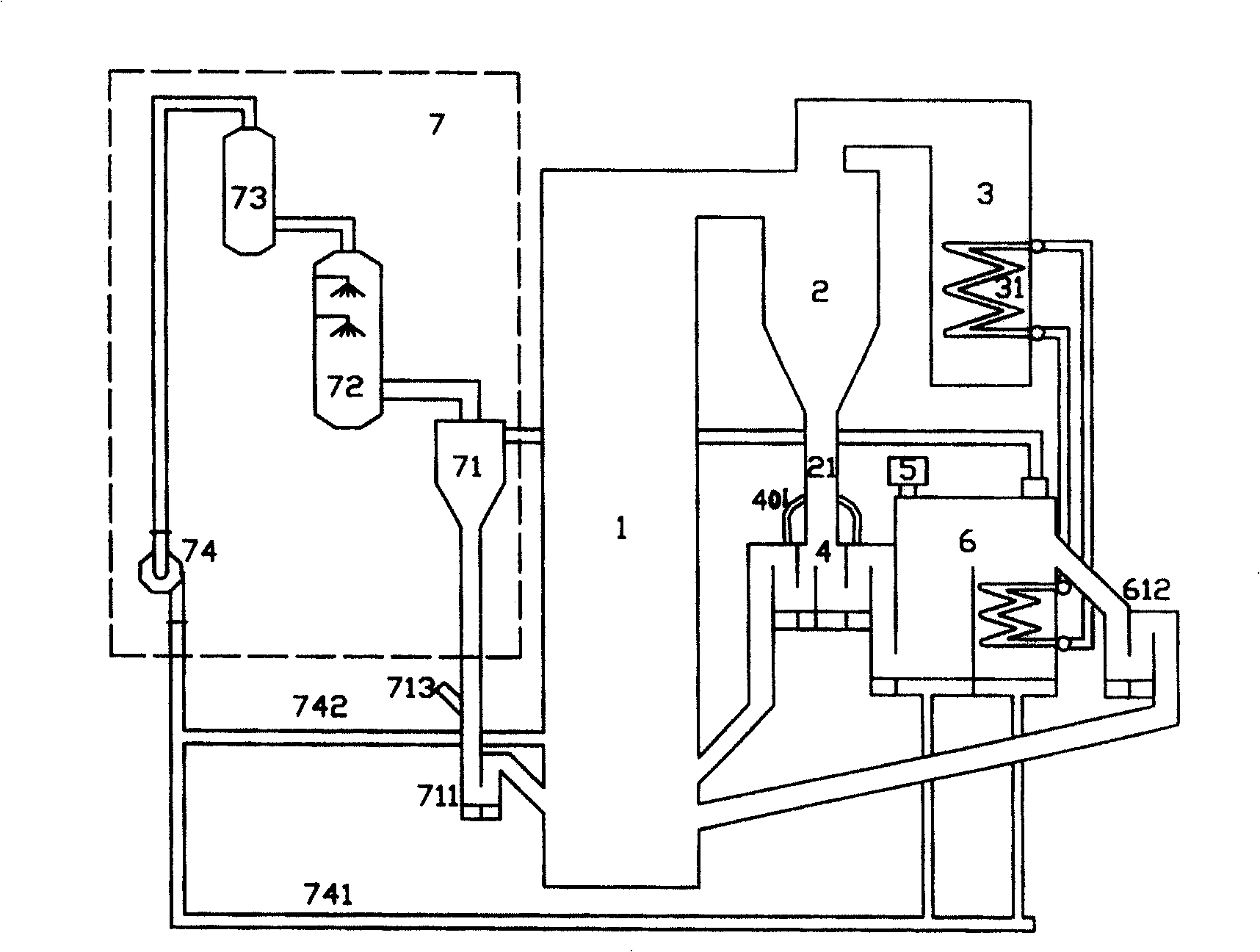
[0037] figure 1 and figure 2 It is a schematic structural diagram of this embodiment. It can be seen from the figure that the wet sludge incineration treatment device with a composite dryer in this embodiment consists of a circulating fluidized bed incinerator furnace 1, a high-temperature gas-solid separator 2, and a tail flue 3 , hot ash distribution valve 4, sludge breaking device 5, composite dryer 6, dryer exhaust treatment system 7 (including fine powder separator 71, cooler 72, steam-water separator 73 and fan 74, etc.).

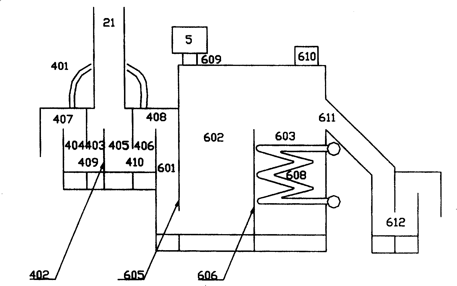
[0038] The hot ash distribution valve 4 is located below the separator 2, the inlet is connected to the material leg 21 of the separator, and the outlet is respectively connected to the incinerator hearth 1 and the composite dryer 6, and its specific structure is:

[0039] A vertical splitter plate 402 is arranged directly below the separator material leg 21, and the first feed chamber 403 and the second feed chamber 405 of hot ash distribution valv...

Embodiment 2

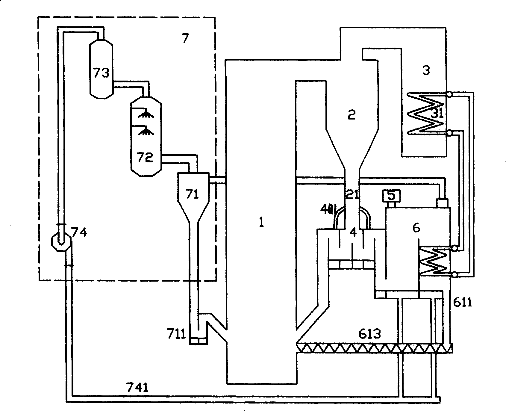
[0049] figure 1 and figure 2 It is a schematic structural diagram of this embodiment. It can be seen from the figure that the wet sludge incineration treatment device with a composite dryer in this embodiment consists of a circulating fluidized bed incinerator furnace 1, a high-temperature gas-solid separator 2, and a tail flue 3 , hot ash distribution valve 4, sludge breaking device 5, composite dryer 6, dryer exhaust treatment system 7 (including fine powder separator 71, cooler 72, steam-water separator 73 and fan 74, etc.).

[0050] The hot ash distribution valve 4 is located below the separator 2, the inlet is connected to the material leg 21 of the separator, and the outlet is respectively connected to the incinerator hearth 1 and the composite dryer 6, and its specific structure is:

[0051] A vertical splitter plate 402 is arranged directly below the separator material leg 21, and the first feed chamber 403 and the second feed chamber 405 of hot ash distribution valv...

Embodiment 3

[0060] A wet sludge incineration treatment device with a composite dryer provided by the present invention is composed of a circulating fluidized bed incinerator hearth 1, a high-temperature gas-solid separator 2, a tail flue 3, a hot ash distribution valve 4, and a sludge blower. Dispersing device 5, composite dryer 6, dryer exhaust treatment system 7 (including fine powder separator 71, cooler 72, steam-water separator 73 and fan 74, etc.).

[0061] The hot ash distribution valve 4 is located below the separator 2, the inlet is connected to the material leg 21 of the separator, and the outlet is respectively connected to the incinerator hearth 1 and the composite dryer 6, and its specific structure is:

[0062] A vertical splitter plate 402 is arranged directly below the separator material leg 21, and its two sides are respectively the first feed chamber 403 and the second feed chamber 405 of the hot ash distribution valve. The projection of the separator dipleg 21 on the bo...


PUM


Abstract

The invention relates to a wet sludge incineration treatment device with a composite dryer. The exhaust gas treatment system is composed of dryer and dryer. The drying and incineration of wet sludge are concentrated in a single device. After the wet sludge is dried in the composite dryer, it returns to the furnace for incineration together with the circulating ash, so that the wet sludge The large amount of moisture contained does not enter the tail flue together with the high-temperature flue gas of the furnace, but is drawn out with the fluidized gas of the composite dryer, which reduces the heat loss of the system; The tube heat exchanger is connected, and the heat brought out of the furnace by the introduction of flue gas, together with the high-temperature circulating ash, is used as a heat source for wet sludge drying, making full use of the residual heat of the incinerator.

Description

technical field [0001] The invention relates to a waste (wet sludge) treatment device, in particular to a wet sludge treatment device which adopts a combination of drying and incineration with a compound dryer. technical background [0002] Sludge is the solid residue after sewage treatment, and the amount of sludge accounts for about 3‰ to 5‰ of the sewage treatment volume (calculated with a water content of 97%). The amount of industrial and domestic sewage treatment in our country is increasing rapidly. With the continuous construction of sewage treatment plants, more sludge will be produced. The composition of sludge is very complex. In addition to a large amount of water, it also contains common organic matter, refractory organic matter, various trace elements, pathogenic microorganisms, parasite eggs, and heavy metals. [0003] The sludge treatment method with incineration as the core process can meet the requirements of reduction, stabilization and harmlessness to th...

Claims


Application Information

Patent Timeline
Patent Type & Authority Patents(China)
IPC IPC(8): F23G5/027F23G5/30F23G5/44C02F11/06
CPCY02W10/40
Inventor 吕清刚那永洁高鸣包绍麟孙运凯贺军矫维红王东宇马人熊贠小银
Owner INST OF ENGINEERING THERMOPHYSICS - CHINESE ACAD OF SCI
Why Eureka
Try Eureka