Method and a transceiver device for transmitting media data via a network
A technology for media data and media transmission, applied in the field of media data transmission via network, can solve the problems of increasing jitter, increasing delay, continuous media stream not being able to tolerate delay and jitter, etc.
Inactive Publication Date: 2008-12-31
IBM CORP
4 Cites 0 Cited by
AI-Extracted Technical Summary
Problems solved by technology
However, continuous media streaming cannot tolerate delay and jitter
Since different paths have d...
Method used
[0041] The transmitter controller 12 of the transmitter device can rely on information about the propagation delay of the data path to select an alternative data path. The purpose of selecting the next data path is to make the propagation delay of the data path closest to the...
Abstract
The invention relates to a method for transmitting media data, in particular speech data, via a network (7), characterized in that said media data is converted into a stream of media data packets. The network has several data paths (P1, P2, P3), including a first and a second data path, each capable of transporting packets of the stream of media packets. The stream of data packets is transmitted via the first data path of the network, such that when a pause in information is detected, the stream of media packets stops via the first data path and begins via the second data path path transfer.
Application Domain
Data switching networks
Technology Topic
Voice dataTransceiver +3
Image
Examples
- Experimental program(1)
Example Embodiment
[0027] For a better understanding of the present invention, its other and further features and advantages, together with the accompanying drawings and the scope of the present invention that will be pointed out in the appended claims, refer to the following description.
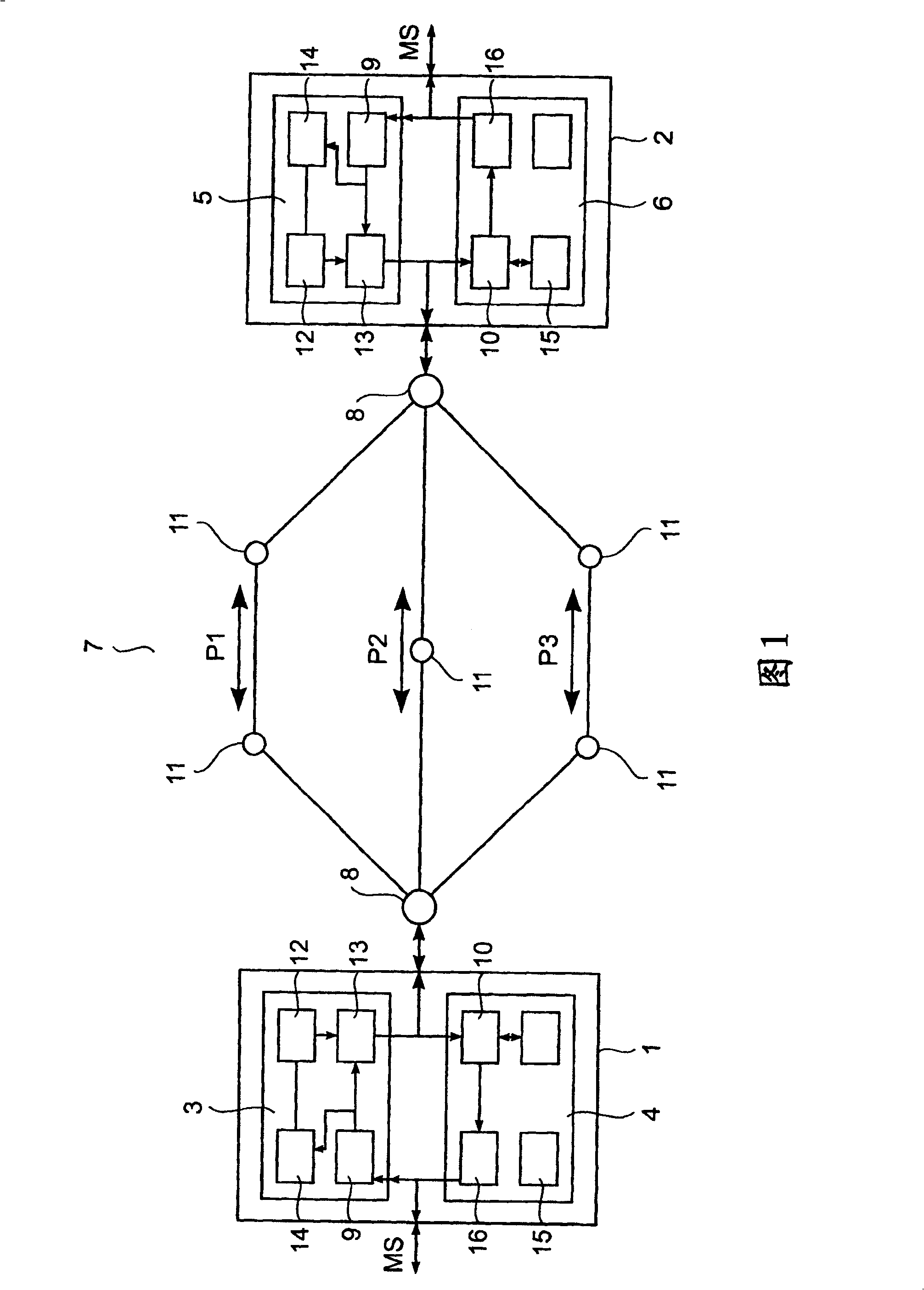
[0028] The only figure shows a simplified network with a first transceiver device 1 and a second transceiver device 2. The first transceiver device 1 includes a first transmitter device 3 and a first receiver device 4, and the second transceiver device 2 includes a second transmitter device 5 and a second receiver device 6. The first and second transceiver devices 1 and 2 are connected via a network 7. The transmitter devices 3 and 5 and the receiver devices 4 and 6 are typically implemented as one device, and the common transceiver devices 1 and 2 have two completely different transmitting and receiving functions. In order to allow the transceiver devices 1, 2 to cope with fast and continuous media streams, the preferred embodiment is in a network processor.
[0029] To allow multiple data paths on the public Internet, overlapping networks are used. Overlapping networks are networks that encapsulate IP in IP, which means that normal IP headers are not used to forward data packets across the network, but are encapsulated in another IP data packet. Encapsulation can be done in encrypted form. The encapsulated IP data packet is used to forward data packets between overlapping network nodes 8 capable of adding and removing encapsulation. This is called an IP tunnel. By dispersing multiple overlapping network nodes 8 throughout the Internet, each interconnected with an IP tunnel, an overlapping network is created.
[0030] Each of the first and second transmitter devices 3, 5 includes a transmission conversion device that can use logic inferred from the media stream to separate the continuous media stream MS on multiple data paths. Each of the first and second receiver devices 4, 6 includes a receiving conversion device 10 capable of recombining multiple sets of media data packets in order to recreate the transmitted media stream.
[0031] In the embodiment of FIG. 1, voice data is provided to the first transceiver device 1 as a media stream. Different data paths P1, P2, P3 are used to transmit the voice data to the second transceiver device 2 across the overlapping network 7. Each of the data paths P1, P2, P3 includes one or more child nodes 11 through which data packets are forwarded. The possible data paths P1, P2, P3 of the first and second transmitter devices 3, 5 are known, either through a special configuration process, or manually installed by an operator.
[0032] The path information is provided by the transmitter controller 12, and the path information it provides indicates which data path of P1, P2, and P3 the media data packet stream should be transmitted through. Each of the transmitter devices 3 and 5 includes a transmitter conversion device 9, which receives the voice stream and divides it into media data packets provided to the transmission device 13. The transmission conversion device provides a time stamp for each generated media data packet, indicating the sequence and time reference of the media data stream.
[0033] The media data packet stream is also received by the pause detector 14, which can recognize that the information in the media stream is paused, for example, by checking the time stamp of the media data packet. In order to detect the information pause by the pause detector 14, it is also possible to directly provide the media stream to the pause detector 14.
[0034] Since natural pauses frequently occur in voice communication, these pauses can be used to change the corresponding data path of the media data packet transmission. As we all know, continuous speech occupies 0.4 to 1.2 seconds, while silence typically lasts 0.6 to 1.8 seconds. This knowledge can be used to detect pauses in voice communications and provide changes to the data path used to deliver media data packet streams. The detection of the information pause is broadcast to the transmitter controller 12, which preferably selects a data path different from the previous data path in order to transmit the media data packet stream via the transmission device 13.
[0035] In order to give the overlapping network node 8 the information of the data paths P1, P2, P3 that should transmit the media data packet stream, the corresponding data path information provided by the controller device 12 or the transmission device 13 can be added—the data path information is added to it To the corresponding data packet of the media data packet stream, or directly provide to the overlapping network node 8-the place where the corresponding data path specified by the data path information is established.
[0036] Preferably, the transmitter controller 12 generates a filler data packet, provides it to the transmission device 13 of the first transmitter device 3, and sends it to a data path different from the transmission media data packet stream. The filler data packet contains Based on the data path information, it tells the second receiver device 6 which data path the media data packet is currently arriving at. The serial number is used to realize the association between the information carried in the filler data packet and the media data packet stream. The path identification is realized by the unit path identifier carried in the payload.
[0037] The second receiver device 6 is used to receive the sent media data packet stream and regenerate the media stream containing voice information. The second receiver device 6 includes receiving means 10 for receiving data packet streams from each data path via the overlapping network node 8. Therefore, the receiving device 10 substantially simultaneously receives the filler data packet and the media data packet. In order to identify which data packet contains the relevant media data, each received data packet is analyzed in the controller 15.
[0038] If the filler data packet is analyzed, the data path information contained in the filler data packet will be identified, and all received data packets transmitted through the data path specified by the data path information given in the filler data packet Both are passed to the conversion device 16, where the received media data packets are recombined to form the original media stream.
[0039] When the receiver controller 15 receives the data packet, it can determine whether it is a voice data packet or a filler data packet, such as through a unique path identifier.
[0040] The transmitter conversion device 9 may include an encryption unit to encrypt the media stream while converting the media stream into a media data packet stream. Similarly, the receiver conversion device 16 may also include a decryption unit, so as to decrypt the received media data packet while converting the media data packet into a media stream.
[0041] The transmitter controller 12 of the transmitter device can select an alternative data path depending on the information about the propagation delay of the data path. The purpose of selecting the next data path is to make the propagation delay of the data path closest to the delay of the data path of the currently transmitted media data packet stream. This provides knowledge and/or prediction for all data path propagation delays. Controlling the switching of the data path based on the propagation delay is beneficial because it can reduce jitter.
[0042] The filler packet matches the media packet. If the filler data packet indicates that several data packets (either media data or filler data) have been sent to the data path, and the corresponding second receiver device 6 does not receive them, it generates path blocking information and sends it to The first transceiver device 1 transmits, giving the first transceiver device 1 information that the corresponding data path should not be used for further transmission. If the interconnection between the first and second transceiver devices 1, 2 is bidirectional, the filler data packet provided by the second transmitter device 5 of the second transceiver device 2 can contain the corresponding path blocking information .
[0043] An attacker who controls part of the packet network can prevent part of the data stream from arriving. Unless they control the entire network, they cannot prevent the entire data stream from being transmitted. Since any part of the data packet stream will inform the receiver device which part of the media stream is propagating, the transmitter device and the receiver device can identify the data path being attacked and delete them from the list of possible data paths.
[0044] By extension, the same technology can be used for multiple separate physical networks. In this case, the attacker needs to control all networks in order to prevent communication. For example, a given transmitter device can access either a fixed Ethernet connected to the Internet or a GPRS connection. In this case, both physical networks can be used for transmission, increasing the barriers to an attacker's successful denial of service. The real-time encryption capabilities, desired security level, and bandwidth requirements of the transmitter and receiver devices may require different changes to the proposed scheme.
[0045] If both the transmitter device and the receiver device have the capability of real-time encryption of encrypted media streams, a high security level can be set. As long as the higher data rate of the data path carrying the media data does not leak difference information, it allows the data path carrying the media data packet stream to be indistinguishable from the data path carrying the filler data packet. This means that these data paths must carry the same throughput. Therefore, filler packets of almost the same size and data rate must be generated in parallel and sent through a data path that does not carry the media packet stream.
[0046] Bandwidth optimization can be implemented by sharing all or part of the data path between different media data packet streams. In this case, filler data packets of different media data packet streams can be transmitted on the same data path, which means that the same media data packet stream requires fewer filler data packets.
[0047] For a less powerful attacker, such as an attacker who can only interfere with one data path at a time and cannot quickly change the data path it interferes with and has lower security requirements, a simpler solution may be sufficient. Then it may be sufficient to exchange data paths regularly, and it may not be necessary to encrypt even the filler data packets between the transmitter device and the receiver device. Therefore, only fewer filler data packets are required, so that the additional bandwidth is not much.
[0048] Since transceiver devices 1 and 2 are usually used in order to establish two-way communication, the transmitter and receiver devices are usually implemented in a network processor. In order to receive corresponding media data packets and reassemble the media data packets into corresponding media streams, the network processor can respectively encrypt and decrypt and/or encode and decode the media streams. In addition, all logic functions, such as the pause detection described above, and the determination of whether the received data packet is a filler data packet or a media data packet, can be executed in the network processor. In addition, the transceiver devices 1 and 2 can also be directly connected to different paths of the network 7, and the overlapping network node 8 is omitted.
PUM


Description & Claims & Application Information
We can also present the details of the Description, Claims and Application information to help users get a comprehensive understanding of the technical details of the patent, such as background art, summary of invention, brief description of drawings, description of embodiments, and other original content. On the other hand, users can also determine the specific scope of protection of the technology through the list of claims; as well as understand the changes in the life cycle of the technology with the presentation of the patent timeline. Login to view more.