Cam rotary feeder of automatic assembler for milled assembled cam shaft

An assembled, camshaft technology, used in assembly machines, valve devices, feeding devices, etc.

Inactive Publication Date: 2009-03-11
JILIN UNIV
View PDF5 Cites 2 Cited by
  • Summary
  • Abstract
  • Description
  • Claims
  • Application Information

AI Technical Summary

Problems solved by technology

This device can solve the problem of feeding and pressing the cam, journal and end when assembling the knurled assembly camshaft

Method used


Image

  • Cam rotary feeder of automatic assembler for milled assembled cam shaft
  • Cam rotary feeder of automatic assembler for milled assembled cam shaft
  • Cam rotary feeder of automatic assembler for milled assembled cam shaft

Examples


Embodiment Construction

[0018] The specific content and working process of the present invention will be further described below in conjunction with the embodiments shown in the accompanying drawings.

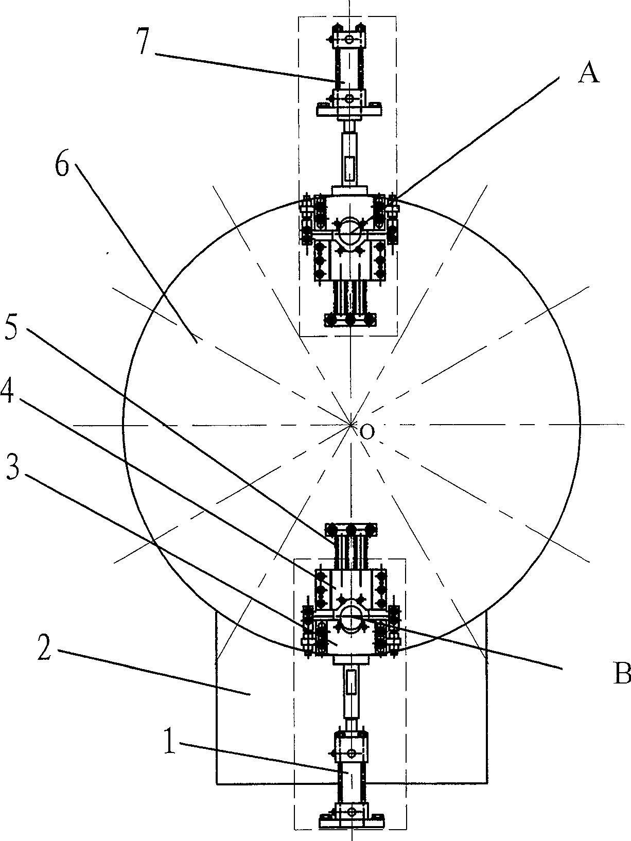
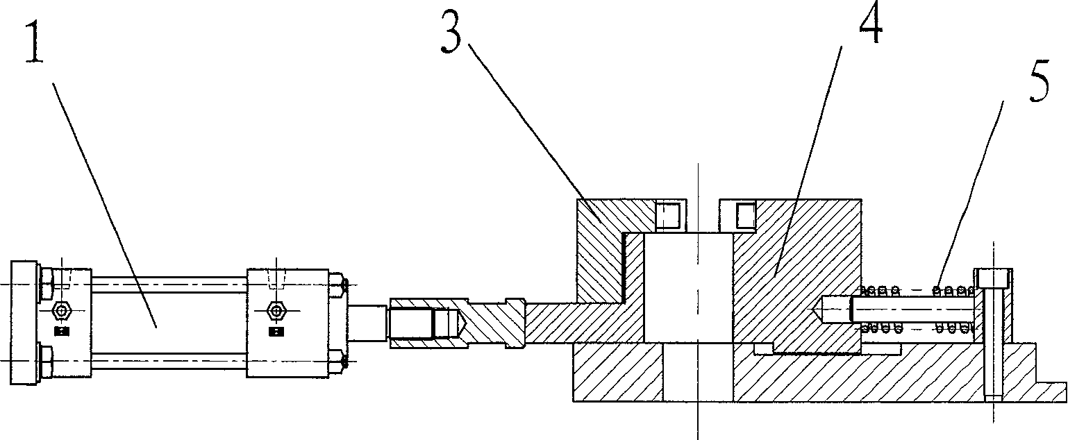
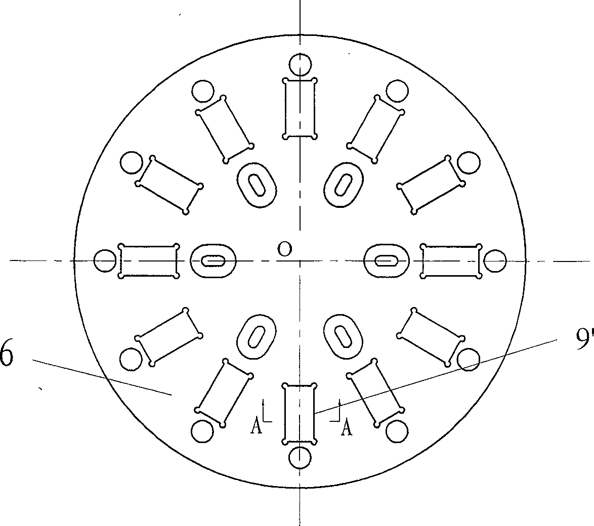
[0019] The rotary disc 6 is placed on the numerically controlled rotary table 2 and can be driven to rotate by the rotary table. A guide rail groove for the positioning and sliding of the moving block 4 is provided on the rotary disc to ensure that the moving block moves along the guide rail groove and the moving block guide rail 9 to ensure assembly accuracy. The moving block guide rail 9 is fixed on the rotary disc 6 .

[0020] The cam feeding oil cylinder 1 is fixed on the outer supporting point, and the cylinder push rod can push the movable block 4 to move toward the center O of the rotary disk along the guide rail groove of the rotary disk 6 and the movable block guide rail 9 . The moving block guide rail 9 is fixed on the rotary disk 6 .

[0021] The cam unloading oil cylinder 7 is fixed on th...


PUM


Abstract

A cam rotating-advancing unit for the automatic assembling machine of assembled knurled cam axle is composed of a numerally controlled rotary bench, a rotary disc on said rotary bench, and the movable block and static block for clamping workpiece. Said movable block is installed in the guide track fixed to said rotary disc and can slide in it. Its rear end is linked with a spring in its holder and its front end is in contact with cam loading or unloading cylinder.

Description

Technical field: [0001] The invention relates to a workpiece feeding device on an assembled camshaft automatic assembly machine. Background technique: [0002] The camshaft is one of the key components of the engine. The traditional manufacturing method is mainly forging or casting blanks as a whole, and then supplemented by a large number of machining. Assembled camshafts are manufactured separately from the mandrel made of hollow steel pipes, cams, journals, and ends, and then assembled into one. Compared with the traditional manufacturing camshaft, the assembled camshaft has the advantages of light weight, easy manufacturing, low production cost and reasonable material utilization. The applicant has applied for and obtained a national invention patent on the "Assembled Camshaft Knurled Connection Automatic Assembly Machine", but the automatic rotary feeding device for cams, journals and ends involved in the automatic assembly machine needs to be further improved. Have n...

Claims


Application Information

Patent Timeline
Patent Type & Authority Patents(China)
IPC IPC(8): B23P21/00B23Q7/02B23Q5/34F01L1/047
Inventor 杨慎华寇淑清张驰金文明何东野赵勇郑祺峰邓春萍
Owner JILIN UNIV
Why Eureka
Try Eureka