Measuring method for axial centroid of two-degree-of-freedom gyroscope rotor assembly

A measurement method and a technology of degrees of freedom, applied in the direction of measuring devices, testing of machines/structural components, instruments, etc., can solve the problems of customized special measuring equipment that cannot meet the requirements, gyroscope parts are scrapped, and the static balance is large, so as to save Manpower and material costs, avoiding repairs or even scrapping, and reducing the effect of temperature drift coefficient

Active Publication Date: 2020-02-21
TIANJIN NAVIGATION INSTR RES INST
View PDF11 Cites 7 Cited by
  • Summary
  • Abstract
  • Description
  • Claims
  • Application Information

AI Technical Summary

Problems solved by technology

[0008] When the weight removal method is used for static balancing, although there is no problem of expansion of the glue on the rotor assembly, it is still often encountered that the static balance is too large, beyond the range that the static balance can remove, and the entire gyro must be disassembled for repair. The strength of the epoxy resin glue is very strong, so it is very easy to cause the gyro-related parts to be scrapped during the disassembly process, so the function of measuring the center of mass is still very important
[0009] Since gyroscopes require precision assembly to obtain high precision, the measurement accuracy of the centroid of the gyroscope rotor assembly needs to reach the micron level, and custom-made special measurement equipment cannot meet the requirements

Method used


Image

  • Measuring method for axial centroid of two-degree-of-freedom gyroscope rotor assembly
  • Measuring method for axial centroid of two-degree-of-freedom gyroscope rotor assembly
  • Measuring method for axial centroid of two-degree-of-freedom gyroscope rotor assembly

Examples


Embodiment Construction

[0034] In order to further understand the invention content, characteristics and effects of the present invention, the following examples are given, and detailed descriptions are as follows in conjunction with the accompanying drawings:

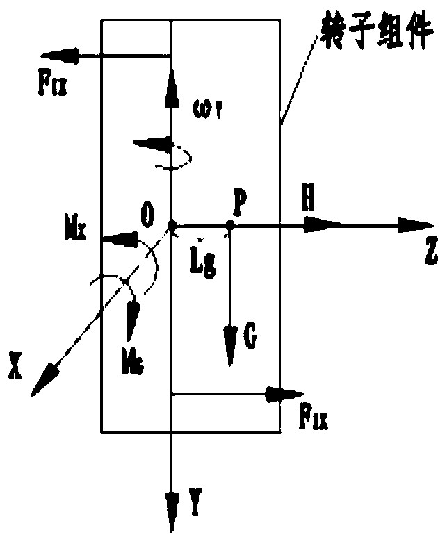
[0035] The present invention is suitable for a two-degree-of-freedom gyroscope, and builds a gyroscope rotor mass center measurement system by means of a gyroscope test system with a force feedback rebalance circuit, focusing on the precise measurement of the axial mass center position of a gyroscope rotor assembly.

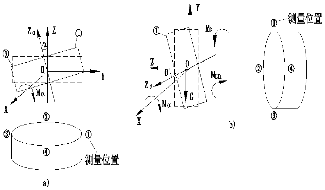
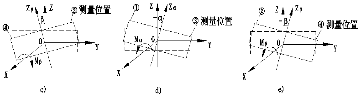
[0036] A method of measuring the precise position of the axial center of mass of a gyro rotor assembly. The physical composition of its measurement system includes a gyro test system, a DC linear power supply, a variable resistance box, and a commutation board. The method is realized through the following steps: firstly, the gyro open-circuit state is in a horizontal posture, at this time, the gyro axis is parallel to the ground...


PUM


Abstract

The invention discloses a measuring method for an axial centroid of a two-degree-of-freedom gyroscope rotor assembly, and belongs to the technical field of angular rate sensors. The measuring method is characterized by comprising the following steps of S1, putting a gyroscope under an open circuit into a horizontal attitude at which point a gyroaxis is parallel to a plumb line of the ground, and adjusting a zero position of a gyro sensor to a minimum value; S2, putting the gyroscope under the open circuit into an azimuth attitude at which point the gyroaxis is perpendicular to the plumb line of the ground, adjusting the zero position of the gyro sensor to a minimum value by inputting current to a gyrotorquer and recording the current value at this moment as IX; S3, measuring an axial unbalance of the gyroscope D(y)y for the gyroscope under a close circuit; S4, establishing a linear relation between the current value IX and the unbalance D(y)y; S5, utilizing the linear relation to calculate the unbalance D(y)y through the measured current value IX. According to the invention, a gyroscope rotor centroid measurement system is built by using a gyroscope test system of a force feedbackrebalance circuit, thereby mainly solving accurate measurement of an axial centroid position of the gyroscope rotor assembly.

Description

technical field [0001] The invention belongs to the technical field of angular rate sensors, in particular to a method for measuring the axial center of mass of a dual-degree-of-freedom gyroscope rotor assembly. Background technique [0002] In the field of inertial navigation and measurement and control technology, centroid measurement is a very important test process. For example, for an aircraft in high-speed motion, when the position of its center of mass is out of tolerance, it will be difficult to adjust its flight direction and attitude, which may easily cause the aircraft to deviate from the track or crash. Therefore, the measurement of the center of mass is of great significance. [0003] The measurement of the center of mass of large objects including rockets, aircraft, missiles and other aircraft, as well as the measurement of the center of mass of small objects including motor rotors, gyro rotors and other parts, all belong to the category of center of mass measu...

Claims


Application Information

Patent Timeline
Patent Type & Authority Applications(China)
IPC IPC(8): G01M1/12G01C25/00
CPCG01C25/005G01M1/122
Inventor 龙春国马本富宋中建胡伟刘祥水郭慧陈成
Owner TIANJIN NAVIGATION INSTR RES INST
Why Eureka
Try Eureka