Transmission line micro processor adaptive split-phase longitudinal difference protection method

A transmission line self-adaptive technology, which is applied in the field of transmission line differential protection using a microcomputer, can solve problems such as protection device misoperation, and achieve improved braking capacity, excellent braking characteristics, and increased braking sensitivity. Effect

Inactive Publication Date: 2009-04-29
贺家李 +2
View PDF1 Cites 0 Cited by
  • Summary
  • Abstract
  • Description
  • Claims
  • Application Information

AI Technical Summary

Problems solved by technology

However, the existing current longitudinal differential protection method for transmission lines has the following problems: when an external short circuit occurs, due to the influence of current transformer errors, line distributed capacitance current and other factors, the transmission line will produce a large imbalance At this time, effective braking measures must be taken, but the various braking methods used in this field cannot not only guarantee a strong braking effect when the external short circuit occurs; Guaranteed braking action with high sensitivity in case of short circuit

Method used


Image

  • Transmission line micro processor adaptive split-phase longitudinal difference protection method
  • Transmission line micro processor adaptive split-phase longitudinal difference protection method
  • Transmission line micro processor adaptive split-phase longitudinal difference protection method

Examples


Embodiment Construction

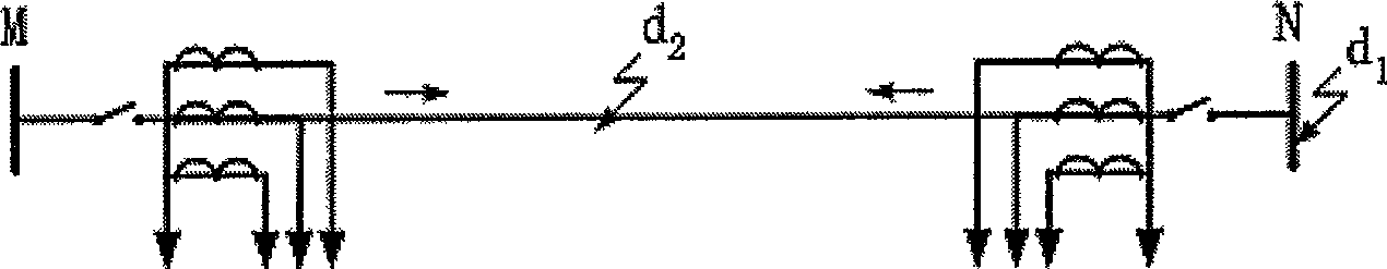
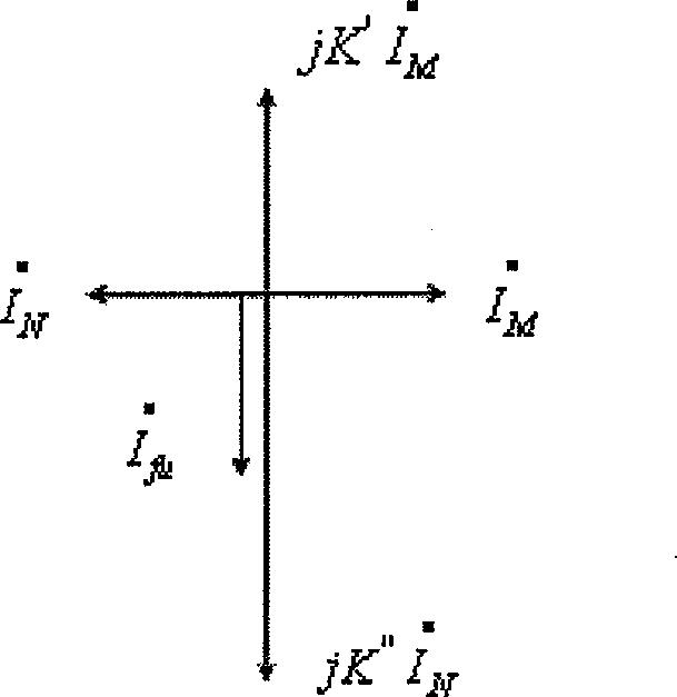
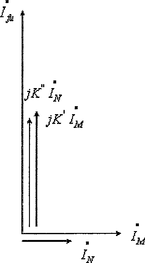
[0023] The schematic diagram of the transmission line protected by the method of the present invention, such as figure 1 As shown, the current amplitude and phase at both ends are compared at the same time, and the adaptive phase-separated longitudinal differential protection of the transmission line is realized by braking the unbalanced current of the transmission line. It is characterized in that the method includes the following steps: taking the two ends of the transmission line For the current vector value, respectively multiply the current at the local end and the current at the opposite end by a coefficient, add the two calculation results, and rotate the current vector obtained after the addition by 90° counterclockwise to obtain the transformed current vector amplitude , and then multiply the transformed current vector magnitude by the current vector magnitude of the local end, and then multiply the calculated result by the sine value of the angle between the local end...


PUM


Abstract

In the invention, protection is realized by comparing with current amplitudes and phases at two ends to brake unbalanced current on transmission line. The method includes steps: multiplying current at local end and current at remote end by coefficient, adding two calculating results; rotating the added current vector 90 degrees widdershins so as to obtain transformed amplitude of current vector; next, multiplying transformed amplitude of current vector by amplitude of current vector at local end; then, multiplying result obtained at previous result by sinusoidal quantity of included angle between local current and current at opposite end to obtain braking action quantity. The method selects action equation based on change of included angle between currents at two ends so as to prevent too large phase angle difference of currents between two ends.

Description

technical field [0001] The invention relates to the field of relay protection for power system transmission lines, in particular to a method for realizing the longitudinal differential protection of transmission lines by using a microcomputer. Background technique [0002] Usually, the current longitudinal differential protection of the transmission line uses the communication channel to connect the protection devices at both ends of the transmission line longitudinally, and transmits the electrical quantity (current, power direction, etc.) at each end to the opposite end, and compares the electrical quantities at both ends. To judge whether the fault is within the range of the line or outside the range of the line, so as to decide whether to brake (or cut off) the protected line. This is the most complete protection method in the field of transmission line differential protection. However, the existing current longitudinal differential protection method for transmission li...

Claims


Application Information

Patent Timeline
Patent Type & Authority Patents(China)
IPC IPC(8): H02H3/28
Inventor 贺家李薛士敏郭征
Owner 贺家李
Why Eureka
Try Eureka