
Motor stator device

A stator and motor technology, applied in the direction of electromechanical devices, electrical components, structural connections, etc., can solve problems such as reducing occupied space, reducing product yield, affecting product image and competitiveness, etc.

Inactive Publication Date: 2009-05-06
YEN SUN TECH CORP
View PDF9 Cites 0 Cited by
  • Summary
  • Abstract
  • Description
  • Claims
  • Application Information

AI Technical Summary

Problems solved by technology

[0005] However, when each conductive pin 125 passes through the corresponding jack 131 of the circuit board 13, the gap between the two is too narrow because the aperture of the jack 131 is almost equal to the diameter of the conductive pin 125, and Because the lead-out wires 127 are soft and easy to break, each lead-out wire 127 must be tightly wound on the corresponding conductive pin 125 to reduce its occupied space, otherwise it is very easy to connect with the circuit board 13. The inner wall surface of the hole 131 is rubbed and collided to form a fracture, so as to affect the electrical connection relationship between the four stator coils 123 and the circuit board 13, so that the stator coils 123 of the stator 12 cannot be effectively energized and excited to drive the fan wheel 15 to rotate, thereby reducing product quality. rate, the product quality is relatively unstable, which will affect the industry's product image and competitiveness

Method used


Image

  • Motor stator device
  • Motor stator device
  • Motor stator device

Examples


Embodiment Construction

[0014] The stator device with motor of the present invention will be described in detail below through preferred embodiments and accompanying drawings.

[0015] Before the present invention is described in detail, it is noted that in the following description, similar elements are denoted by the same numerals.

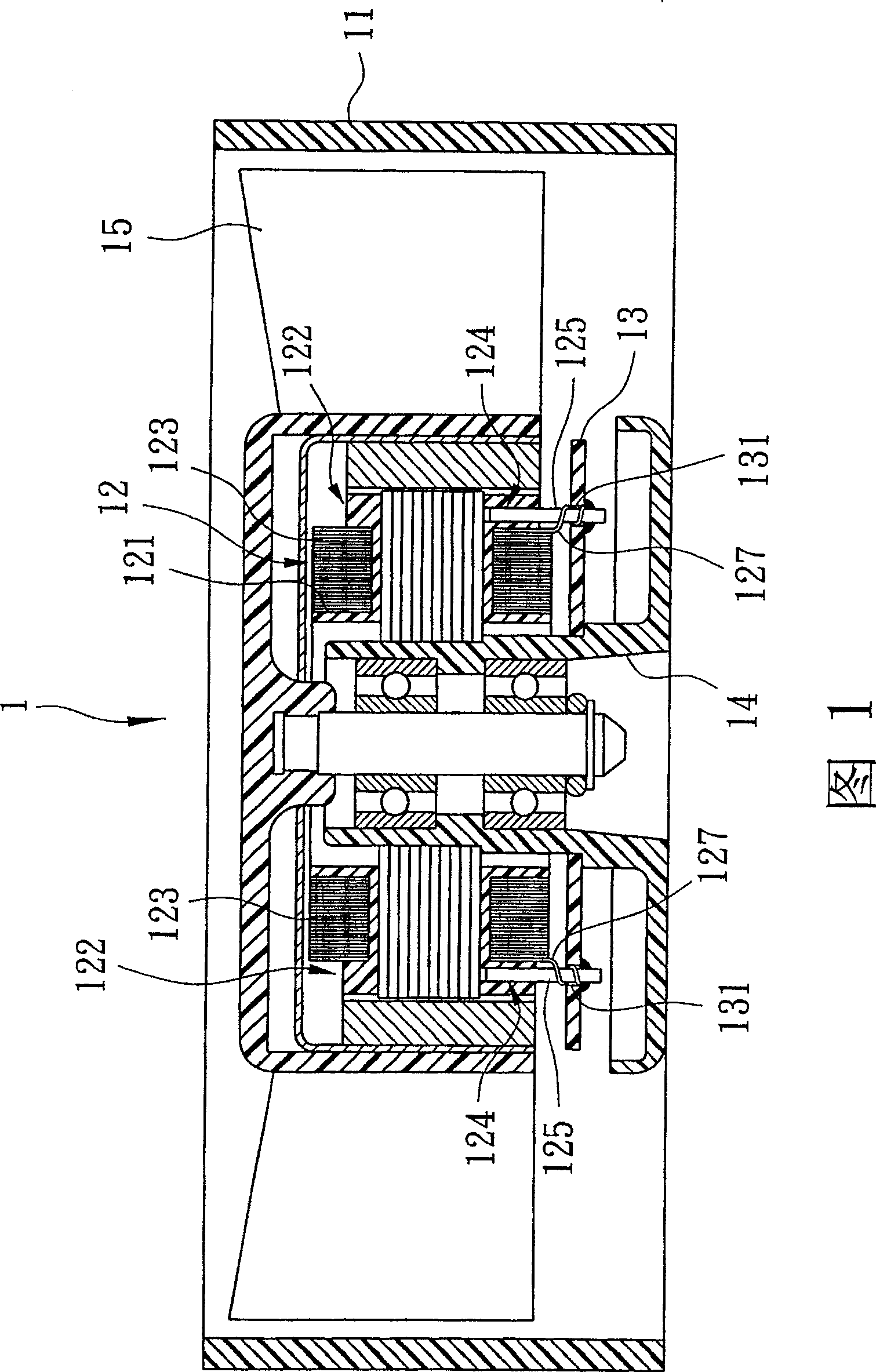
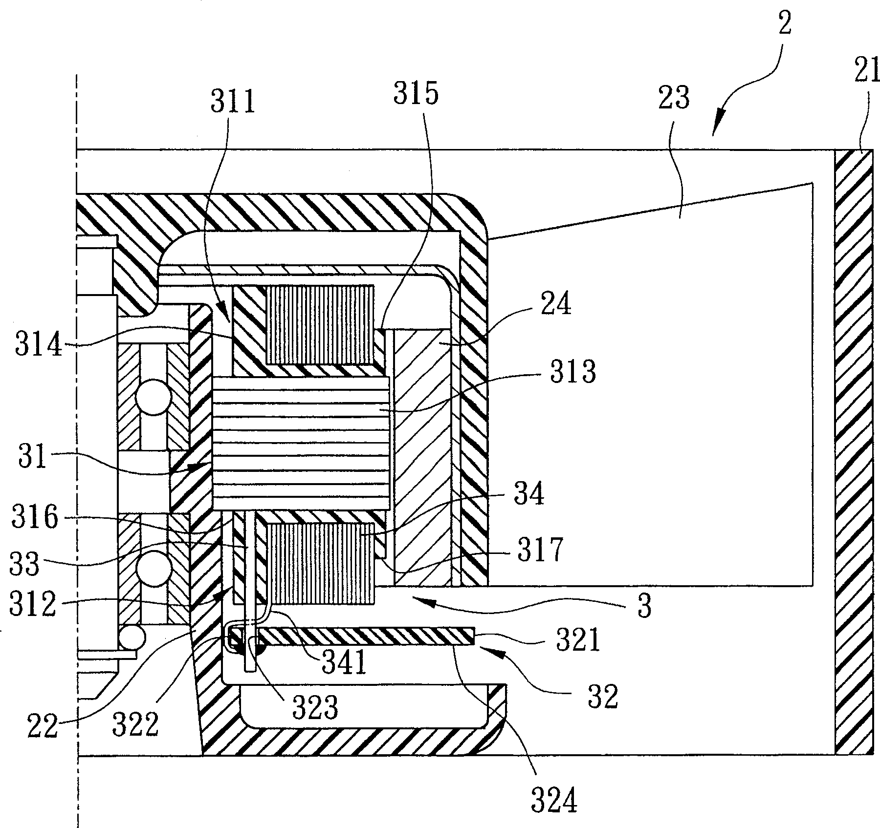
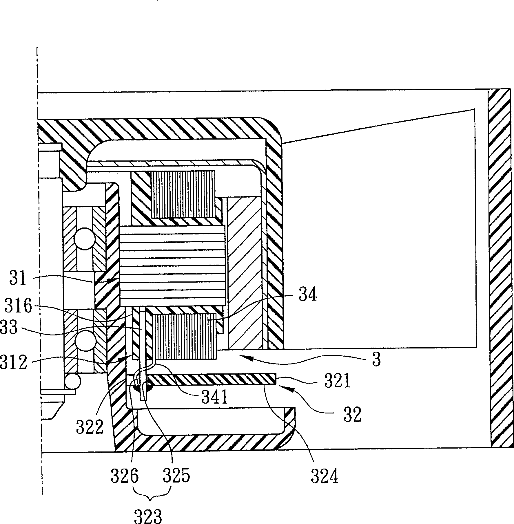
[0016] refer to figure 2 , the first preferred embodiment of the stator device 3 of the motor of the present invention is suitable for being installed in a heat dissipation fan 2, and the heat dissipation fan 2 includes a shell base 21, a shaft tube 22 fixed at the center of the shell base 21, a A fan wheel 23 is rotatably arranged on the shaft tube 22 , and a magnet ring 24 is arranged inside the fan wheel 23 . In this embodiment, the stator device 3 refers to the form installed on the shaft tube 22 of the cooling fan 2, but in actual implementation, the stator device 3 can also be installed in different equipment, such as pumps, electric fans and other equipment, t...


PUM


Abstract

A rotor device of motor includes a stator seat, a circuit board, several conducting pieces, and several stator coils which surrounds the stator seat and possesses a leading wire, the stator possesses a lower insulated rack, and the lower insulated rack possesses a ringer which is provided for said conducting pieces, the circuit board possesses a board body, a interlock hole which through the board body, and several perforations which surround the interlock hole and through the board body, when every conducting piece gets through the corresponding perforations, one end of the projecting part is adjacent the interlock hole, so the leading wire can be get through the interlock hole, and then the rear end can be welded with the board body and relative conducting piece, the leading wire is attrited to hit the wall of the perforations can be avoided, the product quality and stabilization of the invention can be increased.

Description

【Technical field】 [0001] The invention relates to a stator device, in particular to a motor stator device. 【Background technique】 [0002] Referring to Fig. 1, the general fan 1 includes a housing base 11, a stator 12 disposed in the housing base 11, a circuit board 13 connected to the stator 12, and a shaft tube that is sheathed on the stator 12 and the circuit board 13 14, and a fan wheel 15 rotatably sleeved in the shaft tube 14. [0003] The stator 12 has a receiving ring 121 for the shaft tube 14 to pass through, four connecting seats 122 respectively surrounding and connected to the receiving ring 121, and four stator coils 123 respectively wound on the corresponding connecting seats 122. . Each connecting base 122 has a plug-in portion 124 at the bottom, and a conductive pin 125 located on the plug-in portion 124, each stator coil 123 has a lead-out wire 127 that is not wound and fixed, and connects it Wound on the corresponding conductive pin 125 . The circuit bo...

Claims


Application Information

Patent Timeline
Patent Type & Authority Patents(China)
IPC IPC(8): H02K11/00
Inventor 陈建荣刘智光
Owner YEN SUN TECH CORP
Learn More