Optical instrument orientation device for regulating and receiving large power light source

An optical instrument and high-power technology, applied in the field of alignment devices, can solve the problems of reducing device performance and reducing optical efficiency, and achieve the effects of strong practicability, wide adjustment range, and improved adjustment accuracy

Active Publication Date: 2009-06-24
BEIJING BDHLASER SCI & TECH +1
View PDF3 Cites 0 Cited by
  • Summary
  • Abstract
  • Description
  • Claims
  • Application Information

AI Technical Summary

Problems solved by technology

[0002] The device supporting the optical instrument requires that the orientation of the optical instrument is accurate. When the light emitted by the light source is inaccurately irradiated on a certain position of the optical instrument, the optical efficiency will be reduced, thereby reducing the performance of the device.

Method used


Image

  • Optical instrument orientation device for regulating and receiving large power light source
  • Optical instrument orientation device for regulating and receiving large power light source
  • Optical instrument orientation device for regulating and receiving large power light source

Examples


Embodiment 1

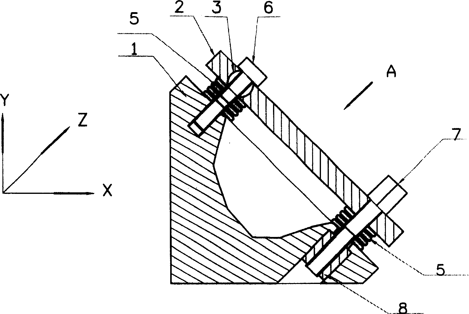
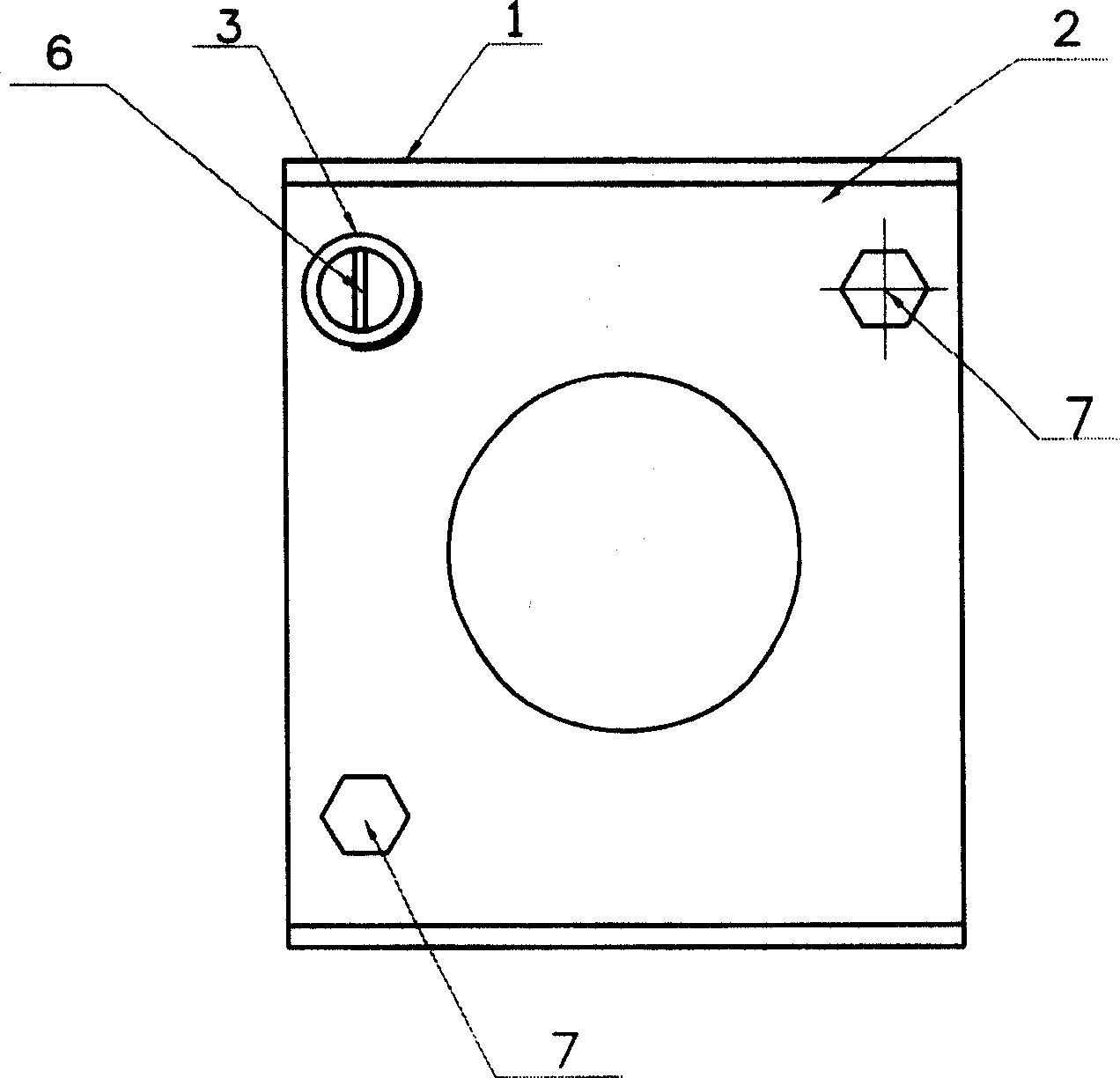
[0027] Embodiment 1: as figure 1 , figure 2 As shown, a high-power light source adjustment frame includes a metal support body 1, a metal adjustment plate 2, a ball head adjustment assembly and two screw adjustment assemblies, and a ball head is placed between the metal support body 1 and the metal adjustment plate 2. The adjustment assembly is connected with two screw adjustment assemblies. The metal support 1 is provided with threaded holes 10 and 11 for installing the ball head adjustment assembly and the screw adjustment assembly. The metal adjustment plate 2 is provided with a concave hemispherical hole 12 for installing the ball head 3 And the mounting hole 14 for installing the adjusting screw 7, the two screw adjusting assemblies are respectively installed on the diagonal position of the metal support body 1 and the metal adjusting plate 2, the advantage of this arrangement is that when adjusting any adjusting screw 7, the metal The adjustment plate 2 will move aroun...

Embodiment 2

[0028] Embodiment 2: as Figure 8 The shown high-power light source adjustment device has the same basic structure as that of Embodiment 1, except that the spring plate 5 of the ball head adjustment assembly should be set between the fixing screw 6 and the metal adjustment plate 2 . The effect of adopting this structure is that it can overcome the defect that the reference point of the metal adjustment plate 2 drifts during the adjustment process caused by the spring piece 5 being arranged between the metal support body 1 and the metal adjustment plate 2 in the first embodiment. Because when adjusting the adjustment screw 7 of a certain adjustment assembly, as the metal adjustment plate 2 moves on the spherical surface of the ball head part 3, the force on each point on the spring leaf 5 is uneven, and the original reference point of the metal adjustment plate 2 will be changed. A certain amount of drift occurs, making it difficult to precisely adjust the angle of the metal ad...

Embodiment 3

[0029] Embodiment 3: as Figure 9 The shown high-power light source adjustment device has the same basic structure as that of Embodiment 2, except that: the metal support body 1 has a through hole 15, and the hemispherical head piece 4 has a cylindrical rear portion 16. There is a threaded hole 17 in the middle of the hemispherical head piece 4 and its cylindrical rear part 16. The cylindrical rear part 16 passes through the through hole 15, and the fixing screw 6 and the threaded hole 17 cooperate with each other to fix and connect the metal adjustment plate 2 and the ball head adjustment. Assemblies and the metal support body 1, the axial direction of the through hole 15 is perpendicular to the working surface of the metal support body 1. The effect of adopting this structure is: the gravity component of the metal adjustment plate 2 originally carried by the fixing screw 6 It is changed to be carried by the cylindrical rear part 16 of the hemispherical head piece 4, which im...


PUM


Abstract

The invention provides a high-power light source adjustment device, which includes a support body, an adjustment plate, a ball adjustment assembly and a screw adjustment assembly. The support body and the adjustment plate are connected by a ball adjustment assembly and a screw adjustment assembly, and the adjustment plate is closely attached to For the spherical movement of the ball head, the connecting line between the screw adjustment assembly and the ball head adjustment assembly is perpendicular to each other, adjusting any screw adjustment assembly can independently change the angle of the adjustment plate relative to the support body in two vertical directions.

Description

technical field [0001] The invention relates to an orientation device for adjusting an optical lens receiving a light source, in particular to an orientation device capable of finely and easily adjusting an optical device receiving a high-power light source. Background technique [0002] The device matched with the optical instrument requires that the orientation of the optical instrument is accurate. When the light emitted by the light source is inaccurately irradiated on a certain position of the optical instrument, the optical efficiency will be reduced, thereby reducing the performance of the device. Therefore, it is required that the adjustment device carrying the optical instrument can be adjusted accurately. At present, widely used optical adjustment devices are mainly used to install light-weight optical components (such as optical glass mirrors, small-sized metal mirrors, etc.), which are mainly used in laboratory environments, but with the development of high-power...

Claims


Application Information

Patent Timeline
Patent Type & Authority Patents(China)
IPC IPC(8): G02B27/00
Inventor 辛建国邬江兴张志远王伟平
Owner BEIJING BDHLASER SCI & TECH
Why Eureka
Try Eureka