Method and apparatus of real-time automatic calibration and compensation for beam drift

An automatic calibration and beam technology, which is applied in the field of precision or ultra-precision optical measurement, can solve the problems of large crosstalk and adjust the beam collimation without involving energy drift, and achieve the effect of high adjustment accuracy and convenient adjustment.

Inactive Publication Date: 2012-06-20
ZHEJIANG UNIV
View PDF4 Cites 40 Cited by
  • Summary
  • Abstract
  • Description
  • Claims
  • Application Information

AI Technical Summary

Problems solved by technology

Although this method partially solves the problem of real-time adjustment of the laser beam, it can be better applied to equipment such as laser collimators, but the adjustment of energy drift and beam collimation

Method used


Image

  • Method and apparatus of real-time automatic calibration and compensation for beam drift
  • Method and apparatus of real-time automatic calibration and compensation for beam drift
  • Method and apparatus of real-time automatic calibration and compensation for beam drift

Examples


Embodiment Construction

[0083] The present invention will be described in detail below in conjunction with embodiments and drawings, but the present invention is not limited to this.

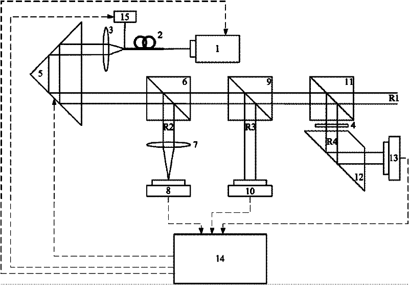
[0084] A real-time automatic correction and compensation device for beam drift, such as figure 1 Shown, including:

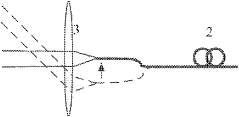
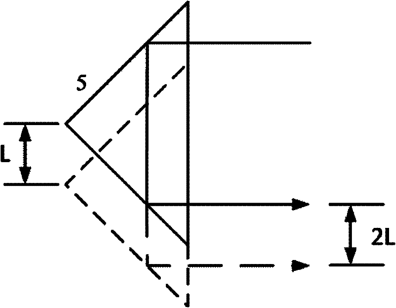
[0085] Laser 1, single-mode fiber 2, collimating lens 3, polarizer 4, corner cube 5, first beam splitter 6, plano-convex lens 7, first photoelectric sensor 8, second beam splitter 9, second photoelectric sensor The device 10, the third beam splitting prism 11, the rhombic prism 12, the third photoelectric sensing device 13, the computer 14 and the nano-translation stage 15, wherein the exit end face of the single-mode fiber 2 is located near the object focus of the collimating lens 3. The translation stage 15 is firmly connected to the exit end face of the single-mode optical fiber 2, and the relative positional relationship between the exit end face of the single-mode optical fiber 2 and the collimating lens...


PUM


Abstract

The invention discloses a method and apparatus of real-time automatic calibration and compensation for beam drift. The method comprises the following steps that: after the primary collimation of a laser beam is conducted, the laser beam sequentially passes through three beam splitter prisms to be split to obtain a bunch of work beams and three bunches of monitoring beams; and the three bunches of monitoring beams are received by corresponding photoelectric sensing devices and are respectively used for monitoring energy drift and angular offset, parallel offset as well as collimation degree drift, and each parameter of the laser beam is adjusted in real time according to the obtained monitoring information. The device comprises a laser, a single-mode fiber, a collimating lens, a pyramid prism, a first beam splitter prism, a plano-convex lens, a first photoelectric sensing device, a second beam splitter prism, a second photoelectric sensing device, a third beam splitter prism, a rhombic prism, a third photoelectric sensing device, a computer and a nano-translation stage. The method and apparatus have the advantages of high adjustment accuracy, large adjustment range, fast and accurate adjustment process, the interference with each other is not generated, and the structure of the apparatus is concise.

Description

Technical field [0001] The invention belongs to the field of precision or ultra-precision optical measurement, and particularly relates to a method and device for real-time automatic correction and compensation of beam drift. Background technique [0002] Laser beams are widely used in various precision or ultra-precision optical observation and measurement equipment due to their good monochromaticity, directivity and high brightness. However, due to the high heat generated by the laser during the excitation process, it is easy to cause the deformation of the system components and the uneven refractive index of the air caused by the temperature and humidity changes in the operating environment. The laser beam is prone to energy drift, parallel shift, angular shift and other reasons. Problems such as the decrease of beam collimation, and the phenomenon will become more serious with the passage of time, which greatly affects the accuracy of precision observation and measurement equ...

Claims


Application Information

Patent Timeline
IPC IPC(8): G02B27/30G02B27/10G01B11/27
Inventor 匡翠方李旸晖郝翔刘旭李帅
Owner ZHEJIANG UNIV
Why Eureka
Try Eureka