Automatic combustor control system for steam power generation station

An automatic combustion and control system technology, applied in the direction of engine starting, controlled combustion, engine components, etc., can solve problems such as wrong operation, wrong control, complex and sensitive burner ignition and extinguishing process

Inactive Publication Date: 2009-07-01
LSIS CO LTD
View PDF5 Cites 0 Cited by
  • Summary
  • Abstract
  • Description
  • Claims
  • Application Information

AI Technical Summary

Problems solved by technology

[0014] As described above, since the burner 20 is manually controlled in consideration of the customer's load change according to the conventional steam power plant, erroneous operation or misoperation occurs during a rapid load change due to a real-time accident of power equipment, and therefore, in Accidents frequently occur during ignition and extinguishment of generators, because the process of ignition and extinguishment of burners is complex and sensitive
In addition, a skilled supervisor must concentrate on controlling the burner 20, so when the supervisor's attention is not concentrated, a control error occurs

Method used


Image

  • Automatic combustor control system for steam power generation station
  • Automatic combustor control system for steam power generation station
  • Automatic combustor control system for steam power generation station

Examples


Embodiment Construction

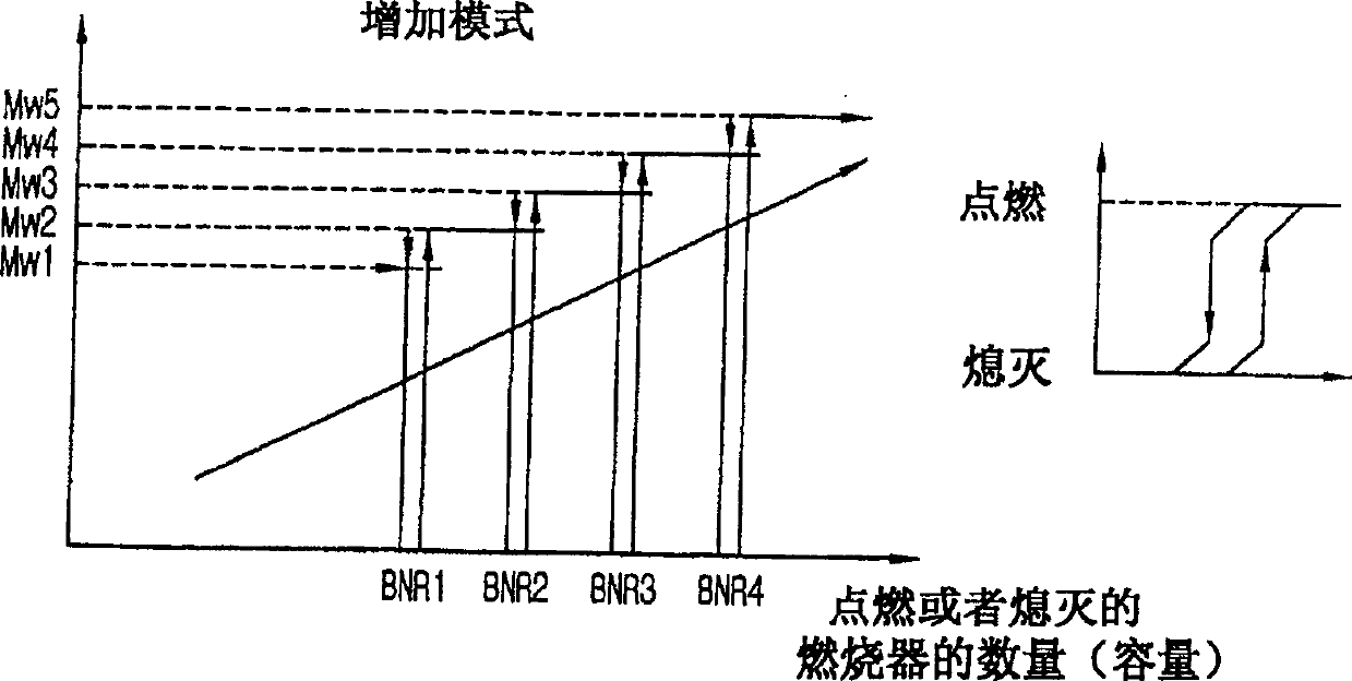
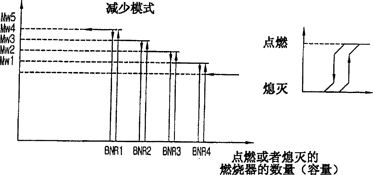
[0027] will refer to the accompanying drawings, namely Figures 4 to 9 , which can be specified in detail based on the characteristic data affecting the ignition and extinguishment of the generator burner (such as the relationship between the output power of the generator and the number of ignited and extinguished burners, the pressure of the burner header and the number of ignited and extinguished burners A preferred embodiment of an automatic burner control system and method thereof for automatically and correctly controlling a group of burners.

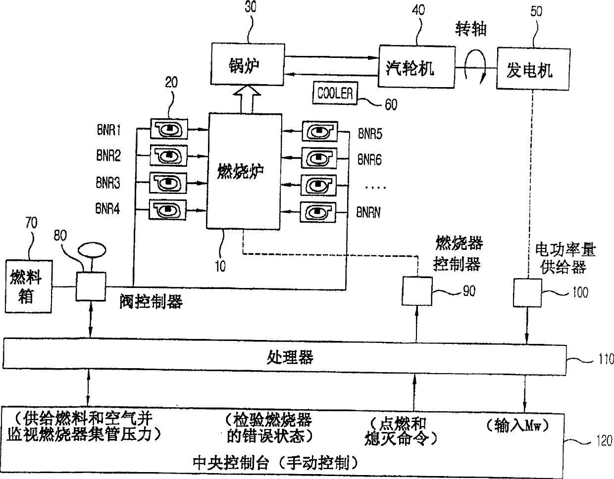
[0028] Figure 4 is a block diagram showing a steam power plant.

[0029] Such as Figure 4 As shown, the steam power station includes: a combustion furnace 10, heated by a plurality of burners BNR1 to BNR20; a boiler 30, which uses the combustion furnace 10 to heat water to generate steam; a steam turbine 40, which uses the steam generated by the boiler 30 to rotate; a generator 50 , connected to a rotating shaft of the steam t...


PUM


Abstract

The present invention provides multiple burners for steam power plants, in particular a system for automatic control of multiple burners. The automatic burner control system includes: a valve controller for measuring and controlling the header pressure of the burner; a power supply for measuring and supplying the power generated by the generator; a central console for setting and providing reference data for controlling firing and extinguishing of the burners and for monitoring error conditions of the burners; and a processor for comparing the reference data supplied from the center console with the measured local header input from the valve controller The data is compared with at least one of the data on the currently measured generated power supplied by the power supplier to automatically control ignition and extinguishment of the burner.

Description

technical field [0001] The present invention relates to multiple burners for steam power plants, and more particularly to a system for automatically controlling the multiple burners. Background technique [0002] Typically, the rotational speed of the steam turbine determines the amount of power produced by the steam power plant. The amount of steam provided by the boiler determines the speed of the turbine. The steam volume of the boiler is determined by the number of burners used to heat the furnace and the header pressure of this burner, that is, by the amount of fuel sent to the burner . Therefore, skilled managers of steam power plants control the number of burners to be ignited and the amount of fuel added according to the customer's load changes. [0003] The following will refer to figure 1 and 2 Describes the operation of the burner used to control the amount of power produced by the generator. [0004] figure 1 is a graph showing the relationship between the...

Claims


Application Information

Patent Timeline
Patent Type & Authority Patents(China)
IPC IPC(8): F01D19/00F01D15/10F23N5/00
Inventor 李承柱
Owner LSIS CO LTD
Why Eureka
Try Eureka