Engine

An engine and fuel technology, applied in combustion engines, engine control, machines/engines, etc., to solve problems such as deterioration of exhaust emissions and deterioration of fuel economy

Inactive Publication Date: 2009-07-01
TOYOTA JIDOSHA KK
View PDF6 Cites 0 Cited by
  • Summary
  • Abstract
  • Description
  • Claims
  • Application Information

AI Technical Summary

Problems solved by technology

As a result, the problems of fuel economy deterioration and exhaust emission (especially NOx) deterioration occur

Method used


Image

  • Engine
  • Engine
  • Engine

Examples


Embodiment Construction

[0027] Hereinafter, the best mode for carrying out the present invention will be described in detail with reference to the accompanying drawings.

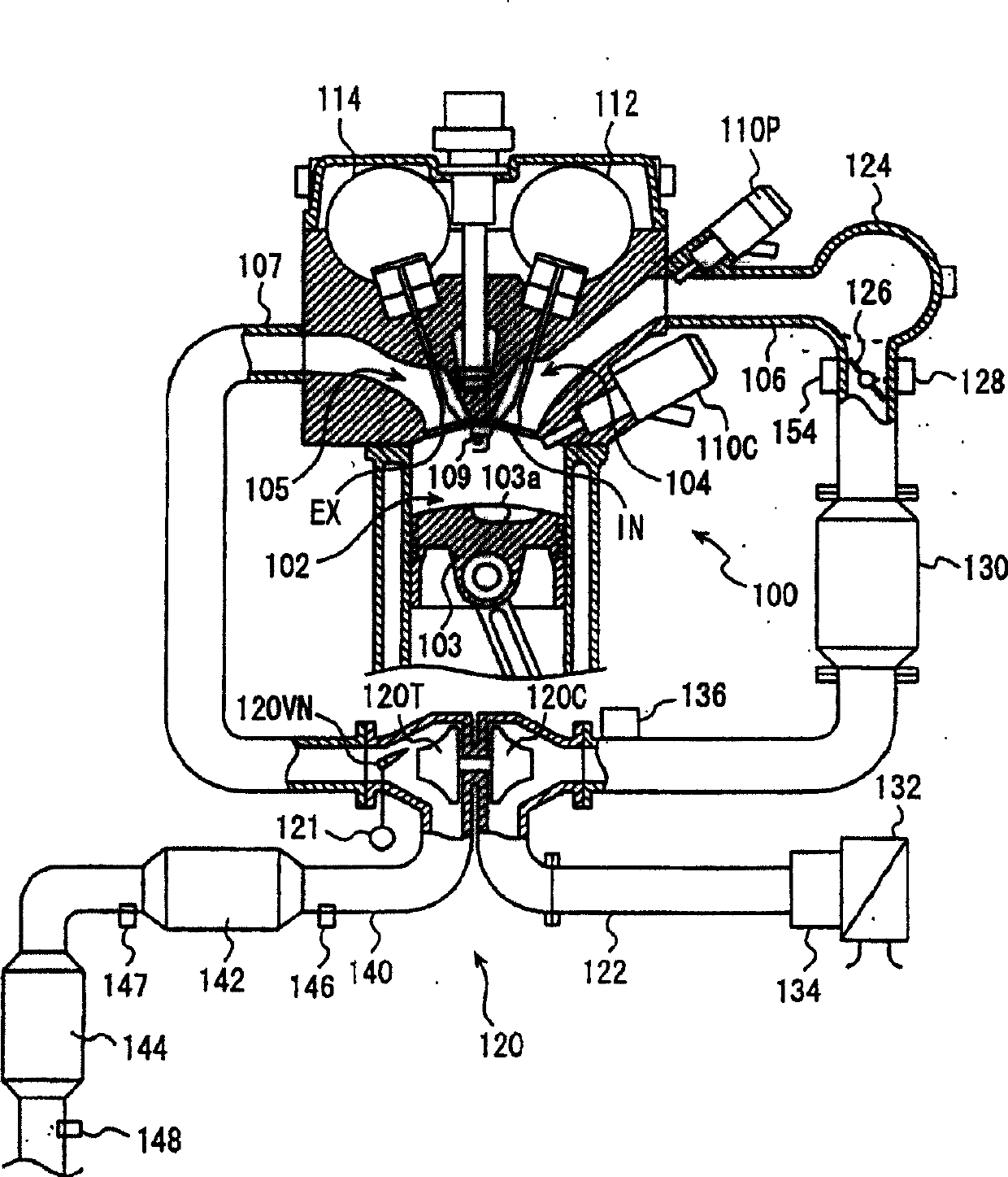
[0028] figure 1 A system structure is schematically shown, which roughly illustrates a lean-burn engine equipped with a supercharger, wherein the engine uses a turbocharger as a supercharger, and according to the first and second embodiments of the present invention applied to the system. figure 1 The illustrated engine 100 is configured as a multi-cylinder engine (eg, a four-cylinder engine, however figure 1 Only one cylinder is shown), an air-fuel mixture is combusted in each combustion chamber 102 to reciprocate a piston 103, thereby deriving power from a crankshaft (not shown). Note that the engine may not have a supercharger.

[0029] Each combustion chamber 102 of engine 100 communicates with an intake port 104 and an exhaust port 105 . An intake manifold 106 is connected to the intake port 104 . An exhaust manifold 1...


PUM


Abstract

The engine includes an in-cylinder injector that injects fuel into a cylinder, an intake port injector that injects fuel into an intake manifold, and a valve opening characteristic changing mechanism that changes at least a lift or opening of an intake valve. duration. When the engine is in a predetermined operating region and the valve opening characteristic changing mechanism reduces the lift or the opening duration of the intake valve, the ratio of fuel injected by the in-cylinder injector increases according to the reduced amount of the lift or the opening duration, The jet thus compensates for the reduction in the tumble ratio.

Description

technical field [0001] The present invention relates to an engine, and particularly to an engine having an in-cylinder injector injecting fuel into a cylinder and a port injector injecting fuel into an intake manifold or an intake port and having a valve opening characteristic changing mechanism. Background technique [0002] In general, a so-called dual-injection type engine is known that has an in-cylinder injector that injects fuel into a cylinder and a port injector that injects fuel into an intake manifold or an intake port, and depending on the operating state of the engine These injectors are used alternately to achieve, for example, stratified-charge combustion when the engine is in a low-load operating region and homogeneous-charge combustion when the engine is in a high-load operating region, or they are used simultaneously at a predetermined fuel injection ratio to achieve Improvements such as fuel economy and output characteristics. [0003] Further, a twin-inje...

Claims


Application Information

Patent Timeline
Patent Type & Authority Patents(China)
IPC IPC(8): F02D41/34F02D41/40F02D41/00
CPCY02T10/44Y02T10/144
Inventor 入泽泰之
Owner TOYOTA JIDOSHA KK
Why Eureka
Try Eureka